A
fault is not a natural occurrence. It is an unplanned event which
occurs unexpectedly. Electrical faults in an electrical installation or
piece of equipment may be caused by //
Negligence – that is, lack of proper care and attention
Misuse – that is, not using the equipment properly or correctly
Abuse – that is, deliberate ill-treatment of the equipment
If the installation was properly designed in the first instance to perform the tasks required of it by the user, then the negligence, misuse or abuse must be the fault of the user.
However,
if the installation does not perform the tasks required of it by the
user then the negligence is due to the electrical contractor in not
designing the installation to meet the needs of the user.
Negligence on the part of the user may be due to insufficient maintenance
or lack of general care and attention, such as not repairing broken
equipment or removing covers or enclosures which were designed to
prevent the ingress of dust or moisture. Misuse
of an installation or pieces of equipment may occur because the
installation is being asked to do more than it was originally designed
to do, because of expansion of a company, for example.
Circuits are sometimes overloaded
because a company grows and a greater demand is placed on the existing
installation by the introduction of new or additional machinery and
equipment.
A common approach to test cable and determine insulation integrity is to use a Hi-pot test.
In a hi-pot test, a DC voltage is applied for 5 to 15 min. IEEE-400
specifies that the hi-pot voltage for a 15-kV class cable is 56 kV for an
acceptance test and 46 kV for a maintenance test
(ANSI/IEEE Std. 400-1980). Other industry standard tests are given in
(AEIC CS5-94, 1994; AEIC CS6-96, 1996; ICEA S-66-524, 1988). High-pot
testing is a brute-force test; imminent failures are detected, but the
amount of deterioration due to aging is not quantified (go/no-go test).
The DC test is controversial
– some evidence has shown that hi-pot testing may damage XLPE cable
(Mercier and Ticker, 1998). EPRI work has shown that dc testing
accelerates treeing (EPRI TR-101245, 1993; EPRI TR-101245-V2, 1995).
For Hi-pot testing of 15-kV, 100% insulation (175-mil, 4.445-mm) XLPE cable, EPRI recommended:
Do not do testing at 40 kV (228 V/mil) on cables that are aged
(especially those that failed once in service and then are spliced).
Above 300 V/mil, deterioration was predominant.
New cable can be tested at the factory at 70 kV. No effect on cable life was observed for testing of new cable.
New cable can be tested at 55 kV in the field prior to energization if aged cable has not been spliced in.
Testing at lower dc voltages (such as 200 V/mil) will not pick out bad sections of cable.
Another option for testing cable integrity: ac testing does not
degrade solid dielectric insulation (or at least degrades it more
slowly). The use of very low frequency AC testing (at about 0.1 Hz) may
cause less damage to aged cable than DC testing (Eager et al., 1997)
(but utilities have reported that it is not totally benign, and ac
testing has not gained widespread usage).
The low frequency has the advantage that the equipment is much smaller than 60-Hz AC testing equipment.
Fault Location
Utilities use a variety of tools and techniques to locate underground faults. Several are described in the next few paragraphs [see also EPRI TR-105502 (1995)].
Divide and conquer
On a radial tap where the fuse has blown, crews narrow down the
faulted section by opening the cable at locations. Crews start by
opening the cable near the center, then they replace the fuse. If the
fuse blows, the fault is upstream; if it doesn’t blow, the fault is
downstream.
Crews then open the cable near the center of the remaining portion
and continue bisecting the circuit at appropriate sectionalizing points
(usually padmounted transformers). Of course, each time the cable
faults, more dam-age is done at the fault location, and the rest of the
system has the stress of carrying the fault currents. Using
current-limiting fuses reduces the fault-current stress but increases
the cost.
Fault indicators
Faulted circuit indicators (FCIs) are small
devices clamped around a cable that measure current and signal the
passage of fault current. Normally, these are applied at padmounted
transformers. Faulted circuit indicators do not pinpoint the fault; they
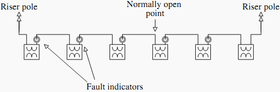
identify the fault to a cable section. Figure 1 - Typical URD fault indicator application
After identifying the failed section, crews must use another method
such as the thumper to precisely identify the fault. If the entire
section is in conduit, crews don’t need to pinpoint the location; they
can just pull the cable and replace it (or repair it if the faulted
portion is visible from the outside). Cables in conduit require less
precise fault location; a crew only needs to identify the fault to a
given conduit section.
Utilities’ main justification for faulted circuit indicators is
reducing the length of customer interruptions. Faulted circuit
indicators can significantly decrease the fault-finding stage relative to
the divide-and-conquer method. Models that make an audible noise or have
an external indicator decrease the time needed to open cabinets.
Utilities use most fault indicators on URD loops. With one fault
indicator per transformer (see Figure 1), a
crew can identify the failed section and immediately reconfigure the loop
to restore power to all customers. The crew can then proceed to
pinpoint the fault and repair it (or even delay the repair for a more
convenient time).
For larger residential subdivisions or for circuits through
commercial areas, location is more complicated. In addition to
trans-formers, fault indicators should be placed at each sectionalizing
or junction box. On three-phase circuits, either a three-phase fault
indicator or three single-phase indicators are available; single-phase
indicators identify the faulted phase (a significant advantage). Other
useful locations for fault indicators are on either end of cable
sections of overhead circuits, which are common at river crossings or
under major highways. These sections are not fused, but fault indicators
will show patrolling crews whether the cable section has failed.
Fault indicators may be reset in a variety of ways. On manual reset
units, crews must reset the devices once they trip. These units are less
likely to reliably indicate faults. Self-resetting devices are more
likely to be accurate as they automatically reset based on current,
voltage, or time. Current-reset is most common; after tripping, if the
unit senses current above a threshold, it resets [standard values are 3,
1.5, and 0.1 A (NRECA RER Project 90-8, 1993)]. With current reset, the
minimum circuit load at that point must be above the threshold, or the
unit will never reset. On URD loops, when applying current-reset
indicators, consider that the open point might change.