Friday, August 12, 2016

Troubleshooting electrical equipment with insulation resistance test instrument

Troubleshooting of electric motors

Insulation resistance testing is performed when troubleshooting electric motors and related equipment. IEEE Standard 43-2000, Recommended Practice for Testing Insulation Resistance of Rotating Machines, recommends the insulation test voltage to apply, based on winding rating, and minimum acceptable values for electric motor windings.
The IEEE also provides typical guidelines for DC voltage to be applied during an insulation resistance test.


In order to obtain meaningful insulation resistance measurements, the technician should carefully examine the systemunder test.

The best results are achieved when the following conditions are met:
  1. The system or equipment is taken out of service and disconnected from all other circuits, switches, capacitors, overcurrent protection devices, and circuit breakers.
    Ensure that the measurements are not affected by leakage current through switches and overcurrent protective devices!
  2. The temperature of the conductor is above the dew point of the ambient air. When this is not the case, a moisture coating will form on the insulation surface, and, in some cases will be absorbed by the material.
  3. The surface of the conductor is free of hydrocarbons and other foreign matter that can become conductive in humid conditions.
  4. Applied voltage is not higher than the system capacity. When testing low voltage systems, too much voltage can overstress or damage insulation.
  5. The system under test has been completely discharged to the ground. The grounding discharge time should be about five times the testing charge time.
  6. The effect of temperature is considered. Since insulation resistance is inversely proportional to insulation temperature (resistance goes down as temperature goes up), the recorded readings are altered by changes in the temperature of the insulating material.
It is recommended that tests be performed at a standard conductor temperature of 68°F (20°C).
When comparing readings to 68°F base temperature, double the resistance for every 18°F (10°C) above 68°F or halve the resistance for every 18°F below 68°F in temperature. For example, a 1 MΩ resistance at 104°F (40°C) will translate to 4 MΩ resistance at 68°F (20°C).

Click here to access full article

Monday, August 8, 2016

How to select a variable frequency drive

Many drive choices are available from a variety of vendors, so some of the basics and best practices are important to follow.

When choosing a variable frequency drive (VFD), several decisions must be made besides the obvious voltage and current selections. Even the name should be decided on, as it is often called a variable speed drive, adjustable speed drive, micro drive and inverter.

In general, a VFD takes an ac power source and converts it into dc power. The speed control portion of the drive uses the dc voltage to create dc pulses in varying frequency to drive the output motor at speeds other than the 3,600 rpm or 1,800 rpm or other speed depending upon the number of poles the motor was designed to operate at using a 60 or 50 Hz ac supply voltage.

How big should the VFD be? The size of the VFD should be chosen based on maximum motor current at peak demand and not chosen based upon motor horsepower. Constant starting, stopping and dynamic loads affects the electronics inside the VFD far more than the effect they have upon the local power bus and a full voltage motor starter. Therefore, peak demand current should be used. Manufacturers may continue to list hp ratings more as an historical rating than as a useful one.

Perhaps the first decision to make when choosing a VFD is to pick between a voltage/frequency (V/F or V/Hz) drive and a vector controller. Both control methods may or may not be used with feedback such as a rotary encoder. In general, most VFD-controlled motors are operated in an open-loop scenario but take advantage of the VFD’s soft start and adjustable speed features.


Click here to access the full article


Thursday, August 4, 2016

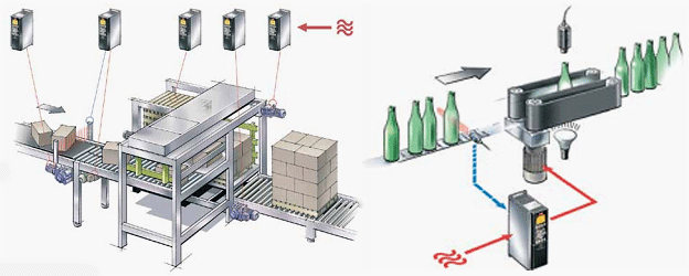
Why do we need variable speed drives (VSD)?

Reasons for using  variable speed drives


There are many and diverse reasons for using variable speed drives. Some applications, such as paper making machines, cannot run without them while others, such as centrifugal pumps, can benefit from energy savings.
In general, variable speed drives are used to:
  1. Latch the speed of a drive to the process requirements
  2. Latch the torque of a drive to the process requirements
  3. Save energy and improve efficiency

The needs for speed and torque control are usually fairly obvious.
Modern electrical VSDs can be used to accurately maintain the speed of a driven machine to within ±0.1%, independent of load, compared to the speed regulation possible with a conventional fixed speed squirrel cage induction motor, where the speed can vary by as much as 3% from no load to full load.


The benefits of energy savings are not always fully appreciated by many users. These savings are particularly apparent with centrifugal pumps and fans, where load torque increases as the square of the speed and power consumption as the cube of the speed.
Substantial cost savings can be achieved in some applications.


An everyday example, which illustrates the benefits of variable speed control, is the motorcar. lt has become such an integral part of our lives that we seldom think about the technology that it represents or that it is simply a variable speed platform. lt is used here to illustrate how variable speed drives are used to improve the speed, torque and energy performance of a machine. It is intuitively obvious that the speed of a motorcar must continuously be controlled by the driver (the operator) to match the trafiic conditions on the road (the process).

In a city, it is necessary to obey speed limits, avoid collisions and to start, accelerate, decelerate and stop when required.

On the open road, the main objective is to get to a destination safely in the shortest time without exceeding the speed limit.

The two main controls that are used to control the speed are the accelerator, which controls the driving torque, and the brake, which adjusts the load torque.
A motorcar could not be safely operated in city traffic or on the open road without these two controls. The driver must continuously adjust the fuel input to the engine (the drive) to maintain a constant speed in spite of the changes in the load, such as an uphill, downhill or strong wind conditions. On other occasions he may have to use the brake to adjust the load and slow the vehicle down to standstill.

Another important issue for most drivers is the cost of fuel or the cost of energy consumption. The speed is controlled via the accelerator that controls the fuel input to the engine.
By adjusting the accelerator position, the energy consumption is kept to a minimum and is matched to the speed and load conditions. Imagine the high fuel consumption of a vehicle using a fixed accelerator setting and controlling the speed by means of the brake position.


Click here to access the full article