Monday, March 23, 2015

Plugging An Overlooked Gap in EMI Defenses


Engineers who design for electromagnetic compatibility (EMC) long ago learned how to to manage EMI through the use of shielded electrical cabinets and high-quality cables with braided shields. But theres a gap in EMI defenses that even experience engineers often fail to notice.

You can find that gap wherever cables enter control cabinets. Oftentimes, the cable connectors at this entry point fail to provide sufficient contact with both the cable shield and the metal cabinet walls.

Fortunately, this gap is easily closed by picking the right cable connectors. These connectors tend to have:

      Low Impedance. To minimize cable shield impedance, the connector contact surfaces

should be as large as possible. Under ideal conditions, the cable shield should function as a continuation of the housing.

      Low Induction. Minimized induction occurs when the cable shielding routes to the housing wall via the shortest possible path and with the widest possible cross-section.

      Full Contact. The best cable connectors will also maintain contact with the shielding around the entire circumference of the cable to ensure there are no discontinuities between shielding and housing once the connection is made.

An example of a cable connector that delivers these characteristics is our new EPIC ULTRA model. It has been designed to improve EMI protection in the crucial juncture between the cable shielding and the control cabinet.

Unlike previous connector models that used finger-like springs to engage the cable shield, EPIC ULTRA features an integrated brush-style EMC fitting. The brush, combined with the nickel-plated housing, creates a conductive shell that functions like a Faraday cage and allows the connector to block external electrical interference.

Even at high frequencies, the brush-style connectors have low impedance and correspondingly high attenuation values. These values suggest that the brush-style grounding integrated in EPIC ULTRA can ensure that EMI defenses are intact from cable to cabinet.

For a more detailed look at our EMI resistant cable connectors and our impedance testing results, download our latest white paper. 


http://landing.lappusa.com/connectorwp

Monday, March 16, 2015

Basic Mechanical Terms used in Drives Applications

Basic Mechanical Terms used in Drives Applications

Terms below are the basic mechanical terms associated with the mechanics of DC drive operation. Many of these terms are familiar to us in some other context.

  1. Force
  2. Net Force
  3. Torque
  4. Speed
  5. Linear Speed
  6. Angular (rotational) Speed
  7. Acceleration
  8. Law of Inertia
  9. Friction
  10. Work
  11. Power
  12. Horsepower


Force

In simple terms, a force is a push or a pull. Force may be caused by electromagnetism, gravity, or a combination of physical means. The English unit of measurement for force is pounds (lb).


Net Force

Net force is the vector sum of all forces that act on an object, including friction and gravity. When forces are applied in the same direction they are added. For example, if two 10 lb forces were applied in the same direction the net force would be 20 lb.

Net force
If 10 lb of force were applied in one direction and 5 lb of force applied in the opposite direction, the net force would be 5 lb and the object would move in the direction of the greater force.


Net force
If 10 lb of force were applied equally in both directions, the net force would be zero and the object would not move.

Net force


Torque

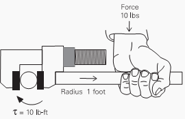
Torque is a twisting or turning force that tends to cause an object to rotate. A force applied to the end of a lever, for example, causes a turning effect or torque at the pivot point.
Torque (tau) is the product of force and radius (lever distance).
Torque (tau) = Force x Radius
In the English system torque is measured in pound-feet (lb-ft) or pound-inches (lb-in). If 10 lbs of force were applied to a lever 1 foot long, for example, there would be 10 lb-ft of torque.

10 lb-ft of torque

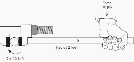
An increase in force or radius would result in a corresponding increase in torque. Increasing the radius to 2 feet, for example, results in 20 lb-ft of torque.

20 lb-ft of torque


Click here to read the full article

Cable Lab Speeds Product Development

When we create new cable technologies, testing has traditionally been one of the biggest bottlenecks in the development process. Even the most minor change to cable materials or structures require a battery of time-consuming tests to ensure compliance with safety standards.

Over the last year, we have eliminated that bottleneck by establishing a comprehensive test lab that allows us to perform Underwriters Laboratories (UL) and related tests in our Florham Park facility.

Certified under the UL Client test Data Program, the lab can handle all the required safety testing:

  • Mechanical testing includes tensile tests for UL 1581 and ASTM D-412, direct burial and crush tests for UL 1277, and exposed run impact tests for UL 1277.
  • Environmental testing includes air-oven aging and oil resistance tests for UL 62 and UL 1581 compliance.
  • Low temperature testing equipment consists of cold impact and cold bend tests required by UL 1581, UL 1277 and UL 444.
  •  Electrical testing includes insulation resistance tests for UL 83 and UL 1581 as well as DC resistance bridge testing for UL 1581 and UL 1277. 
  • Flame testing chambers allow testing for UL 1581, ULVW-1 and UL Horizontal Flame standards.


More Thank UL Testing

Our testing lab goes well beyond the tests needed to satisfy UL requirements. We routinely perform additional testing to support Lapp's proprietary quality and electrical safety standards, some of which address gaps in industry standards. This extra testing requires equipment that is non-standard in cable labs in North America.

Among the unique test cells we operate is large continuous flex machine developed by the Lapp Group in Germany. Measuring 10 meters long, it tests the durability of cable within an energy chain under different duty cycles and bend radii.

Another test machine not normally seen in North American cable development labs is a video microscope that allows us to take precise measurements of the thickness, diameter and concentricity of a cable wires, insulation and jacketing. This dimensional data is used on a daily basis to validate to consistency of our manufacturing processes.

Finally, even some of our "standard" equipment is more advanced than usual. To take two examples, our low temperature impact and crush test cells feature a level of automation that sets them apart from the manual machines normally used for these tests.

Our North American testing lab, which has been operating for over a year, required a major investment. But the lab is already paying dividends for our customers. By bringing the testing in house, jest steps away from our manufacturing lines.


Click here to learn more about our testing capabilities.

Thursday, March 12, 2015

9 Recommended Practices for Grounding

Basis for safety and power quality

Grounding and bonding are the basis upon which safety and power quality are built. The grounding system provides a low-impedance path for fault current and limits the voltage rise on the normally non-current-carrying metallic components of the electrical distribution system.
9 Recommended Practices for Grounding 
During fault conditions, low impedance results in high fault current flow, causing overcurrent protective devices to operate, clearing the fault quickly and safely. The grounding system also allows transients such as lightning to be safely diverted to earth.
Bonding is the intentional joining of normally non-current-carrying metallic components to form an electrically conductive path. This helps ensure that these metallic components are at the same potential, limiting potentially dangerous voltage differences.

 
Careful consideration should be given to installing a grounding system that exceeds the minimum NEC requirements for improved safety and power quality.


1. Equipment Grounding Conductors

The IEEE Emerald Book recommends the use of equipment-grounding conductors in all circuits, not relying on a raceway system alone for equipment grounding. Use equipment grounding conductors sized equal to the phase conductors to decrease circuit impedance and improve the clearing time of overcurrent protective devices.

Equipment grounding conductor
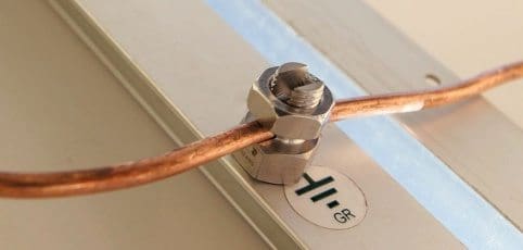
Bond all metal enclosures, raceways, boxes, and equipment grounding conductors into one electrically continuous system. Consider the installation of an equipment grounding conductor of the wire type as a supplement to a conduit-only equipment grounding conductor for especially sensitive equipment.
The minimum size the equipment grounding conductor for safety is provided in NEC 250.122, but a full-size grounding conductor is recommended for power quality considerations.

Click here for the full article