Below is a short list of Frequently Asked Questions about
industrial wire & cable design and applications.
Q: How do you convert the alternating current voltage value (AC)
of a cable into the corresponding direct current voltage value (DC)?
A: The rated voltage
is specified in the form of an AC value (Alternating Current). In a DC system
(Direct Current), the rated voltage of the system must not be greater than 1.5
times of the rated voltage of the cable.
To calculate the DC value, the relevant AC value is simply multiplied by a
factor of 1.5, as in the examples below:
AC Alternating
current Factor DC Direct current
300/500
V x 1.5 450/750 V
450/750
V x
1.5
675/1125 V
600/1000
V x
1.5
900/1500 V
The electrical voltage is measured in Volt (V).
Q: Can the steel wire
armor also be used as EMC-compliant electromagnetic shielding resp. screening?
A: Although copper and
steel are conductive metals, only copper (e.g. in the form of a braid)
represents a suitable means of protecting a cable or wire from electromagnetic
interference or shielding the environment from the interfering emissions
originating from the cable itself. This not only depends on the electrical
conductivity of the metal employed, but also on the braid density or the degree
of coverage with which the cable is braided.
From all metals only
pure silver offers marginally better conductive performance than copper.
Although different qualities of iron/steel alloy exist, the conductivity of
steel is generally six times lower than that of electrolyte copper. For this
reason, a steel wire braid only ever protects a cable from external mechanical
impact. To ensure optimized electromagnetic shielding, which also meets the
requirements of the Electromagnetic Compatibility (EMC) directive, a sufficient
level of copper braiding is required. As a minimum, a visual coverage level of
82-85% is required to achieve adequate screening protection. In the case of a
steel wire braid used solely for mechanical protection, a visual coverage level
of approx. 50% or less is standard. With a little practice, it is therefore
quite easy to visually distinguish copper and steel wire braids by their degree
of coverage. In addition, copper braids often have a slight reddish tinge
(despite their tin plating), are somewhat softer than steel and are in
comparison to steel non-magnetic.
However, even the densest, highest quality copper braid is rendered useless if
it is not properly grounded! For safety reasons, steel wire braids should also
be earthed when used in power networks. If the connected equipment develops a
fault, this grounding prevents the transmission of dangerous voltages to the
often exposed steel wire braid at the connecting points.
Q: Can a data cable
with a peak operating voltage of 250 V be used to connect a device with a mains
voltage of 230 V?
A: No! This could
easily result in fires or lethal electric shocks! Data network cables and power
cables are subject to completely different design and test standards. The main
difference lies in the core insulation strength. Data cables are typically used
in data networks with a voltage range of 6 to 48 V. Connection and control
cables, on the other hand, are predominantly used for devices with a 230 V
mains voltage (e.g. drills, lawnmowers etc.) or for machines in power or
three-phase networks.
Since the size of the voltage is directly connected to the strength of the core
insulation, this represents the greatest difference between data and power
cables.
To be able to cope with voltage ranges of 300/500 V, the core insulation of
power cable, for example, is on average 50-70% thicker than that of a data
cable. It is possible for voltage peaks of 250 V to occur in data networks.
However, under no circumstances must this voltage be equated with a stabilized
alternating current of 230 V at 50 Hz supplied from a mains power socket! Using
a data cable in this case would carry a very high risk of cable fires or
electrocution resulting from the insufficient strength of the core insulation!
The dielectric strength of data cables is generally only checked with 1200 to
1500 V for one minute periods. Connection and control cables, on the other
hand, are tested with 4000 V for periods of 15 minutes.
Indirect connection of data cables to the power network is only possible if a
transformer is used to convert the mains voltage to the permissible low voltage
of the operated device (e.g. a laptop or model railway). In this case, it must
be ensured that cable with the appropriate voltage class (e.g. 300/500 V) is
used to connect the transformer to the mains supply and that the data cable is
only used to link the relevant device with the transformer.
The electrical voltage is measured in Volt (V).
Q: Is it possible to
load a cable or wire with a voltage class of 300/500 V with a higher voltage
for a brief period, provided that the testing voltage value is not exceeded?
A: Heating systems,
for example, require a relatively high voltage to ignite the pilot flame, but
this is only needed once or twice a day and for a matter of milliseconds.
Operators and users are often of the opinion that a cable with a rated voltage
class of, for example, 300/500 V can be briefly supplied with a higher voltage,
provided that it does not exceed the specified testing voltage. In such cases,
it is very important to note that a cable with a rated voltage class of 300/500
V and a testing voltage of, for example, 4000 V must never be subjected a
voltage exceeding the specified rated voltage – not even for a matter of
milliseconds! Even if, for example, a voltage of 2500 V occurs just once per
day for a single second, the relevant cable, and the core insulation thickness
in particular, must be constructed and tested to ensure the appropriate rated
voltage. In this particular case, a cable a with a rated voltage class of 1.8/3
kV must be used to safely handle the briefly occurring voltage of 2500 V.
Q: What is the difference between a copper braid screening and an aluminum
laminated foil screening?
A: Copper braids
primarily protect the cable against inductive coupling in the low frequency
range in which virtually all connecting and control cables operate. If, for
example, a data cable is installed in the direct vicinity of another connecting
cable that may not have copper screen braiding, the data cable should be
protected against inductive interference from the connection cable by means of
a screening braid. The same applies if a connecting cable is installed in the
proximity of an insufficiently shielded or EMC-compliant machine or in the
vicinity of an electric motor, which can also generate fields of inductive
interference.
Aluminum foils are primarily used in data cables, as data is generally
transferred at very high frequencies, thus necessitating protection against
capacitive coupling.
The so-called coupling resistance and the transfer impedance act as indicators
of the shielding performance – the lower the measured transfer impedance, the
greater the effectiveness of the cable screening.
Of course, the best results are achieved by combining a foil shield with copper
screen braiding. The disadvantage is that the aluminum foil laminate makes the
cable quite stiff and inflexible, meaning that it is mostly only really
suitable for fixed installations in conventional cable construction design.
Frequent movement of the cable can quickly tear or displace the sensitive foil
shield, which will have a negative impact on screening performance.
Visit our website
Like us on Facebook
Join our Linkedin Network
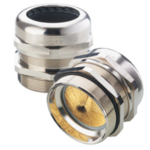 Left unprotected, cable glands
transmit electrical noise that can wreak havoc on motor-driven industrial
processes. Many types of cable glands feature shielding to keep EMI at bay, yet
the effectiveness of that shielding can
vary widely from product to product.
Left unprotected, cable glands
transmit electrical noise that can wreak havoc on motor-driven industrial
processes. Many types of cable glands feature shielding to keep EMI at bay, yet
the effectiveness of that shielding can
vary widely from product to product.