Thursday, December 11, 2014
Global Transfer Switches Market 2014-2018
Global Transfer Switches Market 2014-2018: Reportstack, provider of premium market research reports announces the addition of Global Transfer Switches Market 2014-2018 market report to its offering
Tuesday, November 25, 2014
Friday, November 21, 2014
Thursday, November 13, 2014
Wednesday, November 12, 2014
Characteristics of XLPE insulated cables with reference to the UK standards

Characteristics
of XLPE insulated cables with reference to the UK standards (on photo:
10kV Aluminium Conductor XLPE Insulated Aerial Cable)
Cross-linking effect
XLPE is the recognized abbreviation for cross-linked polyethylene. This and other cross-linked synthetic materials, of which EPR (ethylene propylene rubber) is a notable example, are being increasingly used as cable insulants for a wide range of voltages.Polyethylene has good electrical properties and in particular a low dielectric loss factor, which gives it potential for use at much higher voltages than PVC. Polyethylene has been and still is used as a cable insulant, but, as a thermoplastic material, its applications are limited by thermal constraints.
Cross-linking
is the effect produced in the vulcanization of rubber and for materials
like XLPE the cross-linking process is often described as ‘vulcan-
ization’ or ‘curing’. Small amounts of chemical additives to the polymer
enable the molecular chains to be cross-linked into a lattice formation
by appropriate treatment after extrusion.
The effect of the
cross-linking is to inhibit the movement of molecules with respect to
each other under the stimulation of heat and this gives the improved
stability at elevated temperatures compared with the thermoplastic
materials. This permits higher operating temperatures, both for normal
loading and under short-circuit conditions, so that an XLPE cable has a
higher current rating than its equivalent PVC counterpart.The effects of ageing, accelerated by increased temperature, also have to be taken into account, but in this respect also XLPE has favourable characteristics.BS 5467 specifies construction and requirements for XLPE and EPR-insulated wire-armoured cables for voltages up to 3.3kV. The construction is basically similar to that of PVC cables to BS 6346, except for the difference in insulant. Because of the increased toughness of XLPE the thicknesses of insulation are slightly reduced compared with PVC.

33kV XLPE cable (photo credit: openelectrical.org)
The standard also covers cables with HEPR (hard ethylene propylene rubber) insulation, but XLPE is the material most commonly used. From 3.8kV up to 33kV, XLPE and EPR insulated cables are covered by BS 6622 which specifies construction, dimensions and requirements.
The polymeric forms of cable insulation
are more susceptible to electrical discharge than impregnated paper and
at the higher voltages, where the electrical stresses are high enough
to promote discharge, it is important to minimize gaseous spaces within
the insulation or at its inner and outer surfaces.
To this end XLPE cables for 6.6 kV and above have semiconducting screens
over the conductor and over each insulated core. The conductor screen
is a thin layer extruded in the same operation as the insulation and
cross-linked with it so that the two components are closely bonded. The
screen over the core may be a similar extruded layer or a layer of
semiconducting paint with a semiconducting tape applied over it.Single-core and three-core designs are employed, and there is scope for constructional variation depending on the conditions of use, subject to the cores being surrounded individually or as a three-core assembly by a metallic layer, which may be an armour, sheath or copper wires or tapes.A typical armoured construction which has been supplied in substantial quantities is shown in Figure 1 below.

Figure 1 – XLPE cable construction
Where:
- Circular stranded conductor
- Semiconductor XLPE screen
- XLPE insulation
- Semiconducting tape screen
- Copper tape screen
- PVC filler
- Binder
- Extruded PVC sheath
- Galvanized steel wire armour 10. Extruded PVC oversheath

Underground direct buried power cables
For underground distribution at 11kV, the XLPE cable does not compete economically with the paper-insulated aluminium-sheathed cable, but work is in progress on standardizing and assessing XLPE cable design, including trial installations, in preparation for any change in the situation. Overseas, where circumstances are different, XLPE cable is the type in major demand.
With manufacturing facilities increasingly orientated to this market, XLPE insulated cables constitute a large proportion of UK production.
Tuesday, November 4, 2014
10 Steps to Better Foundation Fieldbus Installations—Part 2
Lessons learned from fieldbus users can help improve systems, performance and personnel. Part one of
this three part series discusses how wiring mistakes interfere with
communication. This installment examines how configuration and
addressing make all the difference. Part 3 addresses working in a
fieldbus environment and will be published in the near future.
Over years of visiting end user sites, talking to system integrators, and internal conversations with others within our own company, tribal knowledge begins to accumulate of what works, what doesn’t and what can be improved. When working in a Foundation fieldbus (FF) context, we find some user companies swear by the technology and won’t consider anything else, while others cannot claim such positive experiences.
When considering what differentiates enthusiastic users from those who gave up, many of the same top 10 points emerge. This series of articles provides details for each point. Here are the Top 10, plus one. (Items 1-4 are discussed here.)
1. Wiring practice pitfalls
2. Terminators
3. Power supplies
4. Stick with tested and registered products
5. Incorrect DD/CFF fles
6. Using the link active scheduler
7. Device addressing
8. Choosing between publisher-subscriber and client-server communication
9. Traditional project management techniques may not apply
10. Mismatch of work processes
11. Misunderstanding the value proposition
This means that when the device is added to a segment, the host automatically reads and performs some configurations to itself and/or the device to communicate correctly. In some cases, the host can self-generate a CFF by reading it from the device.
DD revision management is another issue addressed by automatically reading DD information from each device and keeping this information current on the host control system or asset management system. This functionality is often supported by the supplier via a software upgrade, but it may require manual effort.
LAS functionality can reside in any one of the devices on a segment with link master capability. The scheduled communication cycle to run all the function blocks in all the devices on the segment is known as the segment’s macrocycle, which is the base time (0.5, 1 and 2 seconds are used most commonly) for scheduled communication.
As the number of devices and function blocks to be executed on the segment grows, so will the minimum macrocycle time. The time left over after deterministic communication is made available for responding to other types of requests for information from FF devices, such as diagnostic information or other messages.
Generally, the host system H1 module is automatically configured as the primary LAS. There may be a redundant module in the system that serves as the backup LAS, which works well when LAS redundancy on the H1 I/O modules is desirable. But what is the actual requirement for configuring a backup LAS? If it’s desirable that the segment should keep running despite loss of communication from the host system, then the LAS function needs to reside in one of the devices on the segment.
In some implementations, host redundancy is all that is necessary, as depending upon the configuration of the power and power isolator, a loss of an H1 I/O card will result in a loss of the host’s view of the process, rendering irrelevant LAS redundancy via a device.
Another requirement is power redundancy for a bulk power supply and power isolators. If power to the entire segment is lost, then the location of the LAS function doesn’t matter. However, if the configuration is such that the backup LAS can function without the main power supply because it has its own backup source of power, then that device needs LAS capabilities. Some vendors offer LAS capability within a device for an extra cost, so it’s important only to specify this feature as needed.
Rules for backup LAS in the Foundation fieldbus specification call for the lowest address on the segment to claim LAS first. Upon failure of that device, the next lowest address takes over and so on. Thus, most implementations make the host redundant H1 module the lowest address on the segment.
But, is a third backup configured in a device in addition to the host backup? In practice this is rarely done, either due to an unwillingness to buy such functionality in the device, or by not activating and providing a suitable address when putting the device on the segment. This is often a simple feature to implement and it ensures execution of devices on a segment without the host, and should thus be configured where applicable. Also, if control functionality is being run in a host system, then running a backup LAS in field device is useless.
Many devices come from the factory with a default address. A technician may install the device on the segment without checking the address and then have to figure out why it doesn’t show up on the live list.
He or she often assumes the device is inoperable and uses a bench tool, such as a laptop with Foundation fieldbus interface card or handheld communicator, to scan the segment. Suddenly, the supposedly inoperative device shows up because that tool scans the entire range. This may prompt the technician to check the scan range of the host.
Host systems should generally be configured to access all the variables required for real-time control and display via publisher-subscriber to guarantee update time. Additional data and diagnostic information can then be accessed via client-server on an as-needed basis.
http://insights.globalspec.com/article/171/10-steps-to-better-foundation-fieldbus-installations-part-2
Over years of visiting end user sites, talking to system integrators, and internal conversations with others within our own company, tribal knowledge begins to accumulate of what works, what doesn’t and what can be improved. When working in a Foundation fieldbus (FF) context, we find some user companies swear by the technology and won’t consider anything else, while others cannot claim such positive experiences.
When considering what differentiates enthusiastic users from those who gave up, many of the same top 10 points emerge. This series of articles provides details for each point. Here are the Top 10, plus one. (Items 1-4 are discussed here.)
1. Wiring practice pitfalls
2. Terminators
3. Power supplies
4. Stick with tested and registered products
5. Incorrect DD/CFF fles
6. Using the link active scheduler
7. Device addressing
8. Choosing between publisher-subscriber and client-server communication
9. Traditional project management techniques may not apply
10. Mismatch of work processes
11. Misunderstanding the value proposition
5. Incorrect DD/CFF Files
Let’s say you have a malfunctioning pressure sensor and you decide to replace it with an older unit from inventory. Unfortunately, you discover that it has an older device description (DD) or capabilities file, also known as a common file format (CFF) file. (It’s worth noting that he device descriptor (DD) file allows operation of devices from different suppliers on the same fieldbus with single host system. The common file format (CFF) is an ASCII file which describes the functions and capabilities of a field device. The CFF file is used in conjunction with the DD file to enable a host system to configure the system off-line.) Conversely, you may want to replace an older unit with a newer model with a new DD of CFF file. Either scenario can cause problems, because if the files are different in the host system and the device, then the device will not commission or communicate.
Fortunately,
this legacy problem is being addressed and is disappearing. Suppliers
are tackling this issue by reading DD/CFF files from devices connected
to the host and self-selecting the correct files for the device during
commissioning. This allows for more plug-and-play functionality.
This means that when the device is added to a segment, the host automatically reads and performs some configurations to itself and/or the device to communicate correctly. In some cases, the host can self-generate a CFF by reading it from the device.
DD revision management is another issue addressed by automatically reading DD information from each device and keeping this information current on the host control system or asset management system. This functionality is often supported by the supplier via a software upgrade, but it may require manual effort.
6. Using the Backup Link Active Scheduler
The backup link active scheduler (LAS) is one of the unique capabilities of Foundation fieldbus, but it isn’t used as widely as one might expect. It manages data traffic control to achieve scheduled communication on the segment and it can keep the segment working even when the host system has failed.LAS functionality can reside in any one of the devices on a segment with link master capability. The scheduled communication cycle to run all the function blocks in all the devices on the segment is known as the segment’s macrocycle, which is the base time (0.5, 1 and 2 seconds are used most commonly) for scheduled communication.
As the number of devices and function blocks to be executed on the segment grows, so will the minimum macrocycle time. The time left over after deterministic communication is made available for responding to other types of requests for information from FF devices, such as diagnostic information or other messages.
Generally, the host system H1 module is automatically configured as the primary LAS. There may be a redundant module in the system that serves as the backup LAS, which works well when LAS redundancy on the H1 I/O modules is desirable. But what is the actual requirement for configuring a backup LAS? If it’s desirable that the segment should keep running despite loss of communication from the host system, then the LAS function needs to reside in one of the devices on the segment.
In some implementations, host redundancy is all that is necessary, as depending upon the configuration of the power and power isolator, a loss of an H1 I/O card will result in a loss of the host’s view of the process, rendering irrelevant LAS redundancy via a device.
Another requirement is power redundancy for a bulk power supply and power isolators. If power to the entire segment is lost, then the location of the LAS function doesn’t matter. However, if the configuration is such that the backup LAS can function without the main power supply because it has its own backup source of power, then that device needs LAS capabilities. Some vendors offer LAS capability within a device for an extra cost, so it’s important only to specify this feature as needed.
Rules for backup LAS in the Foundation fieldbus specification call for the lowest address on the segment to claim LAS first. Upon failure of that device, the next lowest address takes over and so on. Thus, most implementations make the host redundant H1 module the lowest address on the segment.
But, is a third backup configured in a device in addition to the host backup? In practice this is rarely done, either due to an unwillingness to buy such functionality in the device, or by not activating and providing a suitable address when putting the device on the segment. This is often a simple feature to implement and it ensures execution of devices on a segment without the host, and should thus be configured where applicable. Also, if control functionality is being run in a host system, then running a backup LAS in field device is useless.
7. Device Addressing
Are all the addresses for devices on a segment in the range that the system is scanning? Some systems scan a finite range in the link-master address range from 20-32 (0x14-0x20) and then at the basic address range 232-248 (0xE8 - 0xF7). This is done to increase performance for sink/source event reporting, and for on-demand communication of parameters to entities such as asset management systems. Knowing this can reduce the chore of finding why some devices don’t appear on the live list, which is the list of devices that reply to the host’s request as being on the segment.Many devices come from the factory with a default address. A technician may install the device on the segment without checking the address and then have to figure out why it doesn’t show up on the live list.
He or she often assumes the device is inoperable and uses a bench tool, such as a laptop with Foundation fieldbus interface card or handheld communicator, to scan the segment. Suddenly, the supposedly inoperative device shows up because that tool scans the entire range. This may prompt the technician to check the scan range of the host.
8. Choosing Between Publisher-Subscriber and Client-Server Communication
Foundation fieldbus supports publisher-subscriber and client-server communication. Some devices have multiple variables available and should use publisher-subscriber for the primary variable and client-server for any other information. This is done to reduce scheduled communication time for the segment since the other information may only be needed upon request and not need to be executed every macrocycle.Host systems should generally be configured to access all the variables required for real-time control and display via publisher-subscriber to guarantee update time. Additional data and diagnostic information can then be accessed via client-server on an as-needed basis.
http://insights.globalspec.com/article/171/10-steps-to-better-foundation-fieldbus-installations-part-2
10 Steps to Better Foundation Fieldbus Installations—Part 1
Lessons learned from fieldbus users can help improve your
systems, performance and personnel. Part one: How wiring mistakes
interfere with communication.
Over years of visiting end-user sites, talking to system integrators and internal conversations with others within our own company, tribal knowledge begins to accumulate of what works, what doesn’t and what can be improved. When working in a Foundation fieldbus (FF) context, we find some user companies swear by the technology and won’t consider anything else, while others cannot claim such positive experiences.
When considering what differentiates enthusiastic users from those who gave up, many of the same top 10 points emerge. Some of the points are specific to Foundation fieldbus and others are more universal, so even if you aren’t a Foundation fieldbus user you might find some familiar topics addressed. Here are the Top 10, plus one:
1. Wiring practice pitfalls
2. Terminators
3. Power supplies
4. Stick with tested and registered products
5. Incorrect DD/CFF files
6. Using the link active scheduler
7. Device addressing
8. Choosing between publisher-subscriber and client-server communication
9. Traditional Project Management Techniques May Not Apply
10. Mismatch of work processes
11. Misunderstanding the value proposition
The first four points are covered in this article. The remaining points are covered in Parts 2 and 3, which will publish soon.
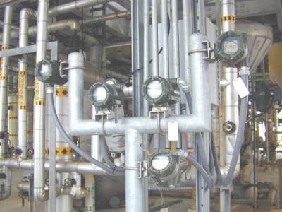
1. Wiring Practice Pitfalls
Good wiring practices apply to all sorts of field devices, but are particularly important with Foundation fieldbus because the digital communication running through the cables is sensitive to electrical noise. Terminations need to be executed properly and Foundation fieldbus cabling should be installed in appropriate cable trays or conduit just like any other field device wiring. So why is this a potential problem area?
Many companies have encountered issues with simple termination and routing rules. In one instance we found high-voltage cables in the same trays with cables from process sensors and actuators. As a result, individual field devices might fall off a segment for a period of time and then mysteriously reappear.
Basic troubleshooting may show a correlation between operating a specific piece of equipment, say a pump controlled by a variable frequency drive (VFD), and device segment drop-offs. If the cables to the VFD are too close to the Foundation fieldbus cables, electrical noise generated by the VFD can disrupt the digital signal. Putting an oscilloscope on the segment can prove the point by showing the offending electrical noise and consequent distorted waveforms.
Other wiring pitfalls relate to device connections. Although many field devices are insensitive to polarity, others are not. As a result, technicians need to pay particular attention.
Here’s a quick quiz: Most Foundation fieldbus cables are brown, blue and green colored wire coverings. Which wire should be positive, the brown wire or the blue one? How is it connected at the H1 module or power isolator?
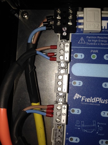
Trying to figure it out by
intuition is a good way to get into trouble. Perhaps you say to
yourself: “Brown represents earth or ground and is therefore negative.
That means blue is for the sky and positive.” There is a certain logic
to that idea but it’s wrong. With Foundation fieldbus, brown is positive
and blue is negative, which provides a guide for hooking up
transmitters, positioners and H1 interfaces. However, the key is
consistency when it comes to which wire is connected to which pole.
Device manufacturers may not help much. Some terminal blocks are more
clearly marked than others. Just because polarity is not obvious does
not mean the device is not sensitive to polarity. To complicate matters
further, Foundation fieldbus cable has three conductors: blue, brown and
a shield, often green or striped green. A given device may also have
three terminals.
Because a Foundation fieldbus cable provides power to the instrument, the normal assumption is that it must follow the same practice as normal power wiring. Standard 120 Vac power has a hot (usually black or some other color), neutral (white) and ground (green or conduit) and everything needs to be properly grounded.
But Foundation fieldbus is first and foremost a communication medium, so a different rule applies: signal wires shall not be grounded. Unfortunately, what sometimes happens is the installer sees three conductors and terminates three conductors. The result is noise on the segment. Hopefully, the installer will know to check the number of Fieldbus terminators (more on that later). If that count is correct, a look at the terminal block will show that the shield is screwed down at the wrong termination. Shields should only be connected to a single point. Most installers now do this at the H1 host or power isolator interface end only.
2. Terminators
Since Foundation fieldbus is a bus system, terminators are placed at each end of the segment to avoid communication reflections which can add noise to the segment and inhibit communication. Technicians typically expect that two terminators on a segment, one near the H1 card and one on the last device on the segment, will solve the problem, but it doesn’t. There can be either too few or too many terminators on the segment, as sometimes one terminator can be too few while three may be too many.
Here’s what can happen: If the segment length is short, there is probably very little noise on the segment whether it has a terminator or not. This situation may have existed in the field for years. But when the day comes when more devices must be added, the decision to use a short segment because there is plenty of room seems perfectly sensible. So the trunk cable is extended from one junction box/tee to another and the overall segment length is increased. Bujt now noise shows up where it hadn’t before. Why?
The problem has to be solved through consistent use of terminators. The best approach isn’t always intuitive and vendors may not be able to help as something as simple as a terminator can vary from company to company. Manufacturer X uses a jumper, manufacturer Y uses a switch and manufacturer Z's product has to be mounted in a junction box.
Fortunately, this issue is becoming less of a problem as Foundation fieldbus ancillary product suppliers have offered more self-terminating junction boxes and power isolators. A wider range of devices is now available that avoids setting jumpers, selecting DIP switches or screwing down connectors in a termination device.
3. Power Supplies
Beware the temptation to use generic, non-Foundation fieldbus rated 24Vdc bulk power supplies, as Foundation fieldbus devices have stringent power requirements.
The Foundation fieldbus specification allows for 9 to 32Vdc power. Applying Ohm’s Law, voltage on a segment will dip slightly as each new device is added and consumes current. But that’s just milliamps and doesn’t affect the voltage too much. The voltage should still remain comfortably within the requirements, well above 9V, but there is more to it. Many factors affect voltage drop along the segment, so power isolators from many vendors are designed to ensure that power is maintained in the 19 to 28Vdc range with little variation regardless of the number of devices drawing current.

That
opens a new set of questions: What capacity (amperage rating) power
supply is needed? Should it be redundant? Should the power isolator be
redundant? Must there be one power supply per segment or is it
appropriate to use a single large unit to power multiple segments?
Again, there are no simple answers, but many guidelines for segment
design are available to deal with voltage and current consumption in
order to answer these questions.
Suppliers are helping as many power isolators now provide segment diagnostics that can be sent to the host or asset management systems. Some can even determine where noise is originating down to individual devices, simplifying troubleshooting.
4. Stick with Tested and Registered Products
The Fieldbus Foundation has instituted a series of testing processes and procedures for devices, host systems and ancillary products to ensure interoperability among products from different suppliers. These tests go through regular reviews and revisions to help users ensure products from different suppliers will work with each other and the host. Suppliers also do their own internal testing with different devices and hosts to minimize risk during product development and to ensure interoperability.
While this sounds sensible, it has not always been the case, and problems may surface when using older devices. In the early days of Foundation fieldbus technology, suppliers often found areas where the specifications had to be interpreted. This caused some interoperability issues. Reviews and revisions over the years have eliminated most of these ambiguities. Foundation fieldbus ancillary products like power isolators, junction boxes, cables and terminators are also tested with the same test criteria and registered at the Foundation.
Coming in Part Two: Keeping device configuration and addressing clear.
http://insights.globalspec.com/article/126/10-steps-to-better-foundation-fieldbus-installations-part-1
Over years of visiting end-user sites, talking to system integrators and internal conversations with others within our own company, tribal knowledge begins to accumulate of what works, what doesn’t and what can be improved. When working in a Foundation fieldbus (FF) context, we find some user companies swear by the technology and won’t consider anything else, while others cannot claim such positive experiences.
When considering what differentiates enthusiastic users from those who gave up, many of the same top 10 points emerge. Some of the points are specific to Foundation fieldbus and others are more universal, so even if you aren’t a Foundation fieldbus user you might find some familiar topics addressed. Here are the Top 10, plus one:
1. Wiring practice pitfalls
2. Terminators
3. Power supplies
4. Stick with tested and registered products
5. Incorrect DD/CFF files
6. Using the link active scheduler
7. Device addressing
8. Choosing between publisher-subscriber and client-server communication
9. Traditional Project Management Techniques May Not Apply
10. Mismatch of work processes
11. Misunderstanding the value proposition
The first four points are covered in this article. The remaining points are covered in Parts 2 and 3, which will publish soon.
1. Wiring Practice Pitfalls
Good wiring practices apply to all sorts of field devices, but are particularly important with Foundation fieldbus because the digital communication running through the cables is sensitive to electrical noise. Terminations need to be executed properly and Foundation fieldbus cabling should be installed in appropriate cable trays or conduit just like any other field device wiring. So why is this a potential problem area?
Many companies have encountered issues with simple termination and routing rules. In one instance we found high-voltage cables in the same trays with cables from process sensors and actuators. As a result, individual field devices might fall off a segment for a period of time and then mysteriously reappear.
Basic troubleshooting may show a correlation between operating a specific piece of equipment, say a pump controlled by a variable frequency drive (VFD), and device segment drop-offs. If the cables to the VFD are too close to the Foundation fieldbus cables, electrical noise generated by the VFD can disrupt the digital signal. Putting an oscilloscope on the segment can prove the point by showing the offending electrical noise and consequent distorted waveforms.
Other wiring pitfalls relate to device connections. Although many field devices are insensitive to polarity, others are not. As a result, technicians need to pay particular attention.
Here’s a quick quiz: Most Foundation fieldbus cables are brown, blue and green colored wire coverings. Which wire should be positive, the brown wire or the blue one? How is it connected at the H1 module or power isolator?
Because a Foundation fieldbus cable provides power to the instrument, the normal assumption is that it must follow the same practice as normal power wiring. Standard 120 Vac power has a hot (usually black or some other color), neutral (white) and ground (green or conduit) and everything needs to be properly grounded.
But Foundation fieldbus is first and foremost a communication medium, so a different rule applies: signal wires shall not be grounded. Unfortunately, what sometimes happens is the installer sees three conductors and terminates three conductors. The result is noise on the segment. Hopefully, the installer will know to check the number of Fieldbus terminators (more on that later). If that count is correct, a look at the terminal block will show that the shield is screwed down at the wrong termination. Shields should only be connected to a single point. Most installers now do this at the H1 host or power isolator interface end only.
2. Terminators
Since Foundation fieldbus is a bus system, terminators are placed at each end of the segment to avoid communication reflections which can add noise to the segment and inhibit communication. Technicians typically expect that two terminators on a segment, one near the H1 card and one on the last device on the segment, will solve the problem, but it doesn’t. There can be either too few or too many terminators on the segment, as sometimes one terminator can be too few while three may be too many.
Here’s what can happen: If the segment length is short, there is probably very little noise on the segment whether it has a terminator or not. This situation may have existed in the field for years. But when the day comes when more devices must be added, the decision to use a short segment because there is plenty of room seems perfectly sensible. So the trunk cable is extended from one junction box/tee to another and the overall segment length is increased. Bujt now noise shows up where it hadn’t before. Why?
The problem has to be solved through consistent use of terminators. The best approach isn’t always intuitive and vendors may not be able to help as something as simple as a terminator can vary from company to company. Manufacturer X uses a jumper, manufacturer Y uses a switch and manufacturer Z's product has to be mounted in a junction box.
Fortunately, this issue is becoming less of a problem as Foundation fieldbus ancillary product suppliers have offered more self-terminating junction boxes and power isolators. A wider range of devices is now available that avoids setting jumpers, selecting DIP switches or screwing down connectors in a termination device.
3. Power Supplies
Beware the temptation to use generic, non-Foundation fieldbus rated 24Vdc bulk power supplies, as Foundation fieldbus devices have stringent power requirements.
The Foundation fieldbus specification allows for 9 to 32Vdc power. Applying Ohm’s Law, voltage on a segment will dip slightly as each new device is added and consumes current. But that’s just milliamps and doesn’t affect the voltage too much. The voltage should still remain comfortably within the requirements, well above 9V, but there is more to it. Many factors affect voltage drop along the segment, so power isolators from many vendors are designed to ensure that power is maintained in the 19 to 28Vdc range with little variation regardless of the number of devices drawing current.
Suppliers are helping as many power isolators now provide segment diagnostics that can be sent to the host or asset management systems. Some can even determine where noise is originating down to individual devices, simplifying troubleshooting.
4. Stick with Tested and Registered Products
The Fieldbus Foundation has instituted a series of testing processes and procedures for devices, host systems and ancillary products to ensure interoperability among products from different suppliers. These tests go through regular reviews and revisions to help users ensure products from different suppliers will work with each other and the host. Suppliers also do their own internal testing with different devices and hosts to minimize risk during product development and to ensure interoperability.
While this sounds sensible, it has not always been the case, and problems may surface when using older devices. In the early days of Foundation fieldbus technology, suppliers often found areas where the specifications had to be interpreted. This caused some interoperability issues. Reviews and revisions over the years have eliminated most of these ambiguities. Foundation fieldbus ancillary products like power isolators, junction boxes, cables and terminators are also tested with the same test criteria and registered at the Foundation.
Coming in Part Two: Keeping device configuration and addressing clear.
http://insights.globalspec.com/article/126/10-steps-to-better-foundation-fieldbus-installations-part-1
Thursday, October 30, 2014
Selection Of Number Of Cable Cores With Emphasis On Sizing Parameters
Dependance On Installation Site
The selection of number of cable cores basically depends on the type of system where it is going to be installed.Generally we have two types of systems:
- A perfectly balanced system and
- A system with some degree of unbalance (or Unbalanced System).
- Cable installation conditions and the load it will carry
- Continuous current rating of the cable
- Voltage drop and short circuit considerations
- Earth fault loop impedance
3-Core Cables
These cables are used generally for a perfect balanced 3-phase system. When the currents on the 3-live wires of a 3-phase system are equal and at an exact 120° phase angle, then the system is said to be balanced. The 3-phase loads are identical in all respects with no need of a neutral conductor.
An important example of 3-phase load is electric motor and that is why, they are fed through 3-Core cables in most cases.
3.5-Core Cables
A 3-phase system may have a neutral wire. This wire allows the 3-phase system to be used at higher voltages while it will still support lower voltage single phase loads.It is not likely in such cases that the loads will be identical, so the neutral will carry the out-of-balance current of the system. The greater the degree of imbalance, the larger the neutral current.

3-5-core cable construction (figure by mitesh-raval.blogspot.com)
When there is some degree of unbalance and the amount of fault current is very small, then 3.5 core cables are used. In these types of cables, a neutral of reduced cross section as compared to the 3-main conductors is used, which is used to carry the small amount of unbalanced currents.
4-Core Cables
When there is severe out-of-balance conditions, the amount of fault current will raise to a very high level. Generally in the case of linear loads, the neutral only carries the current due to imbalance between the phases.
4-core PVC insulated and sheathed copper conductor power cable
The non-linear loads such as switch-mode power supplies, computers, office equipment, lamp ballasts and transformers on low loads produce third order harmonic currents (Definition of Harmonics and Their Origin) which are in the phase of all the supply phases.
These currents do not cancel at the star point of a three-phase system as do normal frequency currents, but add up, so that the neutral carries very heavy third harmonic currents.
That is why the neutral of the cable feeding the equipment are not reduced and made with cross sectional area same as that of the main conductor to carry this high amount of current.
5 and 6-Core Cables
Some conditions may arrive when the amount of fault (neutral) current becomes very large than the phase currents. When the load concerned to this type of situation is fed through a multi-core cable, it is necessary to use a 5-Core or 6-Core Cable.
5-core PVC insulated and sheathed copper conductor power cable
In this condition, two (or three) conductors can be used in parallel formation to carry the high amount of generated unbalanced currents.
Thursday, October 16, 2014
Keep Your Equipment Up to Date for Efficiency
 Many
manufacturing companies operate on thin margins, so wringing every drop
of efficiency out of your equipment is crucial to profitability. This
is especially important in food manufacturing, where consumers are often
price sensitive. In addition, unplanned line stoppages or processing
delays can result in scrap or spoilage of high cost ingredients or
products. Here are eight simple tips to keep your equipment properly
maintained and running smoothly.
Many
manufacturing companies operate on thin margins, so wringing every drop
of efficiency out of your equipment is crucial to profitability. This
is especially important in food manufacturing, where consumers are often
price sensitive. In addition, unplanned line stoppages or processing
delays can result in scrap or spoilage of high cost ingredients or
products. Here are eight simple tips to keep your equipment properly
maintained and running smoothly.
Plan preventive maintenance
The
most important thing you can do to keep equipment running smoothly is
to follow the manufacturer’s recommendations for scheduling preventive
maintenance. Your team may have to perform some maintenance activities
after a period of elapsed time or after a certain level of production.
Keep a log for each piece of equipment to be certain that the team is on
top of the recommended maintenance.
Part of the
maintenance program should be to inspect all components and to replace
them at the first sign of wear. Replacing parts before they fail can
prevent unplanned downtime. If you can, upgrade components such as wire
and cable to higher quality replacements that have a longer expected
life or that can withstand more stress.
Stock spare parts
Many
manufacturers provide a recommended spares list. If possible, stock the
items that fail most frequently. It’s a good idea to stock items such
as wires, cables and shear pins so you can get back up and running
quickly in the event of a problem.
Choose cables and components that stand up to your environment
Food
manufacturing can be a hostile environment for electrical and
mechanical equipment. Long hours of continuous operation processing
acidic or abrasive foods followed by frequent cleaning with water, heat
and chemicals are a normal part of the day in the food industry, but
perhaps not for electrical equipment.
When you
replace wires and cables, be sure to select materials designed for this
harsh environment. The quality and reliability of such simple items as
wires and cables directly affects the performance and reliability of
your food processing equipment.
Firmware updates
Much
of the equipment in use in today’s factories includes computerized
components that may require periodic updating. Part of your preventive
maintenance program should be monitoring the equipment company’s support
website to be on the alert for software or firmware updates. Up-to-date
software may improve the equipment’s efficiency and prevent possible
problems that could cause disruption during production. It’s worth the
time to check and update a machine’s firmware if it can help prevent
unplanned downtime.
Calibration
Part
of your preventive maintenance program should be calibration of your
equipment, but you may also need to adjust your gauges and calibration
tools. Scales and measuring devices can get out of alignment or their
accuracy may deteriorate over time. You can’t calibrate your equipment
if your gauges are off, and lack of calibration may result in improperly
mixed or otherwise poor-quality product.
Operator training
Poorly
trained operators may cause equipment malfunctions or unnecessary wear
and tear on equipment because of improper or inefficient procedures.
While it takes time and effort to train operators in proper setup and
operation of equipment, it pays off in the long run with higher-quality
product, less scrap and rework, more throughput and less unplanned
downtime. Properly trained operators can improve efficiency and extend
the life of your equipment.
Periodic inspections
Even
though you have a preventive maintenance program in place, you might
want to add a periodic inspection to your activities list. Inspecting
machines for unexpected signs of wear allows you to keep equipment in
peak condition. You may want to replace the original equipment wires and
cables with higher quality, more reliable counterparts designed to
withstand the rigors of your environment. Not only will this prolong the
life of the equipment, it may also prevent unplanned downtime due to
equipment failures.
Cleanliness and hygiene
Especially
in food processing, cleanliness is a manufacturing imperative. Spills
and dried-on gunk attract insects and vermin that may choose to snack on
your equipment as well as your product. Of course, you do everything
you can to stay compliant with government regulations for cleanliness,
but cleanliness is more than a regulatory hassle. It can increase
productivity and improve quality in addition to prolonging the life of
your equipment.
Keeping your equipment in peak
condition improves performance. It reduces unplanned downtime due to
breakdowns, improves production efficiency and throughput, and improves
the quality of your product.
Choosing the right fieldbus
How do you find the ideal fieldbus for your needs? There is no single fieldbus that can fulfill all requirements for every application. There can be considerable differences in communication requirements for different applications, therefore the fieldbus must be selected according to these requirements.
Most users want to select a simple communication method that fulfils the requirements of their application. The selected standard is supposed to have appropriate devices and tools for the application.
Apart from ensuring that the chosen device can accept multi-vendor products, users should consider the following:
* Topology
* Access to the fieldbus
* Physical features
* Protocol
* Access rights in multimaster systems
* Noise immunity
* Transmission speed.
Other consideration needs to be given to the technical, communications and system safety requirements. For a complete list, visit the Online Features section of www.mro-esource.com and click on "Choosing the right fieldbus."
Below is a checklist to consider:
Number of nodes
This is the number of devices connected to the field bus or bus segment. This varies from a maximum of 64 nodes with DeviceNet to 247 nodes with Modbus. If, for example, you have an application with 100 drives and want to control from DeviceNet then you will need two DeviceNet scanners.
Transmission speed
Also referred to as Baud rate. The higher the transmission speed the shorter the bus length. The maximum bus segment cable length is defined in the fieldbus standard, such as DeviceNet, Profibus etc., for the supported Baud rates.
Extent of user data
The extent of user data can be limited, depending on either hardware (ASICs, defined by node manufacturer) or software (protocol, defined by the fieldbus standard). This is usually defined in the fieldbus node User Manual.
Topology
The topology usually comes with rules defining how the nodes are connected to one another. The topolgy also defines bus termination rules. This is defined by the fieldbus standard and can be bus, ring, star topology etc.
Modularity, expansion possibilities
Because there is a single cable, the system can be easily constructed in a modular way. This allows the system to be easily expanded later. Machine manufacturers can build their systems based on a modular concept (flexibility).
Noise immunity
Due to reduced amount of cabling there is much less chance to pick up disturbances. Digital technology means drift is eliminated.
Cable requirements
These are defined by the fieldbus standard. Each fieldbus type has its own cable requirements, for example, cross-sectional area, impedance, stray capacitance, etc
Connection cost
Connecting a single cable is much easier than connecting a variety of analogue signal cables. The method of connection is usually standardised.
Device replacement without bus interruption
In daisy-chain bus topology, the bus cable can be removed from the device without interrupting the bus communication. With point-to-point or ring connection, bus communication will always be lost.
Requirements of the application
Type of fieldbus is selected according to the response time required by the application and/or the amount of nodes to be connected to the system
Communication
Required data transfer capacity
Usually the amount of I/O data to be exchanged via the bus
Guaranteed response time
Depending on the bus cycle time, determined by the amount of connected nodes, selected transmission speed and extent of data frame
SYSTEM SAFETY
System safety in a fault situation
Usually the standard fieldbus topology is not redundant but can be made so in many cases. In none redundant bus systems, the action in case of a communication loss can be configured within the nodes, for example fault or remain in operation etc
Safety of data transfer (error recognition)
The safety of the data transfer differs from fieldbus to fieldbus and is defined within the fieldbus protocol
Special attention towards power supply solutions
Some fieldbus systems supply the nodes via the fieldbus cable (DeviceNet) and others require an external power supply (Profibus) to feed the nodes
Readiness of diagnostic tools
For the open fieldbus standards a large variety of diagnostic tools from several manufacturers are available
Tuesday, October 14, 2014
Cable Spacing as a Mean to Noise Mitigation
Separation distances
In situations where there are a large number of cables varying in voltage and current levels, the IEEE 518-1982 standard has developed a useful set of tables indicating separation distances for the various classes of cables.There are four classification levels of susceptibility for cables.
Susceptibility, in this context, is understood to be an indication of how well the signal circuit can differentiate between the undesirable noise and required signal. It follows that a data communication physical standard such as RS-232E would have a high susceptibility, and a 1000-V, 200-A AC cable has a low susceptibility.
IEEE 518 – 1982 standard
The four susceptibility levels defined by the IEEE 518 – 1982 standard are briefly:Level 1 (High) - This is defined as analog signals less than 50 V and digital signals less than 15 V. This would include digital logic buses and telephone circuits. Data communication cables fall into this category.
Level 2 (Medium) - This category includes analog signals greater than 50 V and switching circuits.
Level 3 (Low) - This includes switching signals greater than 50 V and analog signals greater than 50 V. Currents less than 20 A are also included in this category.
Level 4 (Power) - This includes voltages in the range 0–1000 V and currents in the range 20–800 A. This applies to both AC and DC circuits.
Both cables contained in a separate tray:
- Level 1 to level 2-30 mm
- Level 1 to level 3-160 mm
- Level 1 to level 4-670 mm
- Level 1 to level 2-30 mm
- Level 1 to level 3-110 mm
- Level 1 to level 4-460 mm
- Level 1 to level 2-30 mm
- Level 1 to level 3-80 mm
- Level 1 to level 4-310 mm.
Trays and conduits

Cable tray/conduit (photo credit: Legrand)
A few words need to be said about the construction of the trays and conduits. It is expected that the trays are manufactured from metal and be firmly earthed with complete continuity throughout the length of the tray. The trays should also be fully covered preventing the possibility of any area being without shielding.
Briefly galvanic noise
can easily be avoided by refraining from the use of a shared signal
reference conductor, in other words, keeping the two signal channels
galvanically separate so that no interference takes place.
Physical separation between the noise source and the receptor will also reduce magnetic coupling and therefore the interference.
Twisting of signal conductors
Twisting of signal conductors is another way to reduce EMI. The polarity of induced voltage will be reversed at each twist along the length of the signal cable and will cancel out the noise voltage. These are called twisted pair cables.")
Multishield cable (Foil and Braid) – photo credit: multicable.com
Electrostatic interference can be prevented or at least minimized by the use of shields. A shield is usually made of a highly conductive material such as copper, which is placed in the path of coupling. An example is the use of a shield, which is placed around a signal conductor.
When a noise voltage
tries to flow across the capacitance separating two conductors, say a
power and a signal conductor (actually through the insulation of the
conductors), it encounters the conducting screen, which is connected to
ground. The result is that the noise is diverted to ground through
the shield rather than flowing through the higher impedance path to the
other conductor.
If the shield is not of a high conductive material, the flow of the diverted current through the shield can cause a local rise of voltage in the shield, which can cause part of the noise current to flow through the capacitance between the shield and the second conductor.Shielding of Power Cables
Medium
and high-voltage power cables, in circuits over 2000 volts, usually
have a shield layer of copper or aluminum tape or conducting polymer. If
an unshielded insulated cable is in contact with earth or a grounded
object, the electrostatic field around the conductor will be
concentrated at the contact point, resulting in corona discharge, and
eventual destruction of the insulation.
As well, leakage current and capacitive current through the insulation presents a danger of electrical shock. The grounded shield equalizes electrical stress around the conductor, diverts any leakage current to ground. Be sure to apply stress relief/ cones at the shield ends, especially for cables operating at more than 2Kv to earth.
 Shields on power cables are connected to earth
ground at each shield end and at splices for redundancy to prevent shock
even though induced current will flow in the shield. This current will
produce losses and heating and will reduce the maximum current rating of
the circuit. Tests show that having a bare grounding conductor adjacent
to the insulated wires will conduct the fault current to earth quicker.
On high current circuits the shields might be connected only at one
end.
Shields on power cables are connected to earth
ground at each shield end and at splices for redundancy to prevent shock
even though induced current will flow in the shield. This current will
produce losses and heating and will reduce the maximum current rating of
the circuit. Tests show that having a bare grounding conductor adjacent
to the insulated wires will conduct the fault current to earth quicker.
On high current circuits the shields might be connected only at one
end.On very long high-voltage circuits, the shield may be broken into several sections since a long shield run may rise to dangerous voltages during a circuit fault. However, the shock hazard of having only one end of the shield grounded must be evaluated for the risk!
Shielding of an electric power cable is accomplished by surrounding the assembly or insulation with a grounded, conducting medium. This confines the dielectric field to the inside of this shield.

Two distinct types of shields are used:
- Metallic
- Nonmetallic
The purposes of the insulation shield are to:
- Obtain symmetrical radial stress distribution with the insulation.
- Eliminate tangential and longitudinal stresses on the surface of the insulation.
- Exclude from the dielectric field those materials such as braids, tapes, and fillers that are not intended as insulation.
- Protect the cables from induced or direct aver-voltages. Shields do this by making the surge impedance uniform along the length of the cable and by helping to attenuate surge potentials.
Conductor Shielding
In cables rated over 2,000 volts, a conductor shield is required by industry standards. The purpose of the semiconducting, also called screening, material over the conductor is to provide a smooth cylinder rather than the relatively rough surface of a stranded conductor in order to reduce the stress concentration at the interface with the insulation. Conductor shielding has been used for cables with both laminar and extruded insulations.The materials used are either semiconducting materials or ones that have a high dielectric constant and are known as stress control materials. Both serve the same function of stress reduction.
Conductor shields for paper insulated cables are either carbon black tapes or metallized paper tapes. The conductor shielding materials were originally made of semiconducting tapes that were helically wrapped over the conductor. Present standards still permit such a tape over the conductor. This is done, especially on large conductors, in order to hold the strands together firmly during the application of the extruded semiconducting material that is now required for medium voltage cables.
Experience with cables that only had a semi conducting tape was not satisfactory, so the industry changed their requirements to call for an extruded layer over the conductor.
In extruded cables, this layer is now extruded directly over the conductor and is bonded to the insulation layer that is applied over this stress relief layer. It is extremely important that there be no voids or extraneous material between those two layers.
A water-impervious material can be incorporated as part of the conductor shield to prevent radial moisture transmission. This layer consists of a thin layer of aluminum or lead sandwiched between semiconducting material. A similar laminate may be used for an insulation shield for the same reason.
There is no definitive standard that describes the class of extrudable shielding materials known as “super smooth, super clean”. It is not usually practical to use a manufacturer’strade name or product number to describeany material. The term “super smooth, super clean” is the only way at this writing to describe a class of material that provides a higher quality cable thanan earlier version. This is only an academic issue since the older type of materials are no longer used for medium voltage cable construction by known suppliers. The point is that these newer materials have tremendously improved cable performance in laboratory evaluations.
Insulation Shielding For Medium-Voltage Cables
The insulation shield for a medium voltage cable is made up of two components:- Semiconducting or stress relief layer
- Metallic layer of tape or tap , drain wires, concentric neutral wires, or a metal tube.
Stress Relief Layer
The polymer layer used with exbuded cables has replaced the tapes shields that were used many years ago. This extruded layer is called the extruded insulation shield or screen. Its properties and compatibility requirements are similar to the conductor shield previously described except that standards require that the volume resistivity of this external layer be limited to 500 meter-ohms.The nonmetallic layer is directly over the insulation and the voltage stress at that interface is lower than at the conductor shield interface.. This outer layer is not required to be bonded for cables rated up to 35 kV. At voltages above that, it is strongly recommended that this layer be bonded to the insulation .
Since most users want this layer to be easily removable, the Association of Edison Illuminating Companies (AEIC) has established strip tension limits. Presently these limits are that a 1/2 inch wide strip cut parallel to the conductor peel off with a minimum of 6 pounds and a minimum of 24 pounds of force that is at a 90º angle to the insulation surface.
Metallic Shield
The metallic portion of the insulation shield or screen is necessary to provide a low resistance path for charging current to flow to ground. It is important to realize that the extruded shield materials will not survive a sustained current flow of more than a few milliamperes. These materials are capable of handing the small amounts of charging current, but cannot tolerate unbalanced or fault currents.The metallic component of the insulation shield system must be able to accommodate these higher currents. On the other hand, an excessive amount of metal in the shield of a single-conductor cable is costly in two ways. First, additional metal over the amount that is actually required increases the initial cost of the cable. Secondly, the greater the metal component of the insulation shield, the higher the shield losses that result h m the flow of current in the central conductor.
A sufficient amount of metal must be provided in the cable design to ensure that the cable will activate the back-up protection in the event of any cable fault over the life of that cable. There is also the concern for shield losses.
It therefore becomes essential that:
- The type of circuit interrupting equipment to be analyzed.What is the design and operational setting of the hse, recloser, or circuit breaker?
- What fault current will the cable encounter over its life?
- What shield losses can be tolerated? How many times is the shield to be grounded? Will there be shield breaks to prevent circulating currents?
Concentric Neutral Cables
When concentric neutral cables are specified, the concentric neutrals must be manufactured in accordance with ICEA standards. These wires must meet ASTM B3 for uncoated wires or B33 for coated wires.These wires are applied directly over the nonmetallic insulation shield with a lay of not less than six or more than ten times the diameter over the concentric wires.
Shielding Of Low Voltage Cables
 Shielding
of low voltage cables is generally required where inductive
interference can be a problem. In numerous communication,
instrumentation, and control cable applications, small electrical
signals may be transmitted on the cable conductor and amplified at the
receiving end. Unwanted signals (noise) due to
inductive interference can beaslargeasthedesiredsignal. This can result
in false signals or audible noise that can effect voice communications.
Shielding
of low voltage cables is generally required where inductive
interference can be a problem. In numerous communication,
instrumentation, and control cable applications, small electrical
signals may be transmitted on the cable conductor and amplified at the
receiving end. Unwanted signals (noise) due to
inductive interference can beaslargeasthedesiredsignal. This can result
in false signals or audible noise that can effect voice communications.Across the entire frequency spectrum, it is necessary to separate disturbances into electric field effects and magnetic field effects.
Electric Fields
Electric field effects are those which are a function of the capacitive coupling or mutual capacitance between the circuits. Shielding can be effected by a continuous metal shield to isolate the disturbed circuit fiom the disturbing circuit.Even semiconducting extrusions or tapes supplemented by a grounded dmin wire can serve some shielding function for electric field effects.
Magnetic Fields
Magnetic field effects are the result of a magnetic field coupling between circuits. This is a bit more complex thanfor electrical effects.At relatively low frequencies, the energy emitted from the source is treated as radiation. This increases with the square of the frequency. This electromagnetic radiation can cause dislxrbancesat considerable distance and will penetrate any “openings” in the shielding. This can occur with braid shields or tapes that are not overlapped. The type of metal used in the shield also can effect the amount of disturbance.
Any metallic shield material, as opposed to magnetic metals, will provide some shield due to the eddy currents that are set up in the metallic shield by the impinging field. These eddy currents tend to neutralize the disturbing field. Non-metallic, semiconducting shielding is not effective for magnetic effects. In general, the most effective shielding is a complete steel conduit, but thisis not always practical.
The effectiveness of a shield is called the “shielding factor” and is given as:
SF = Induced voltage in shield circuit / Inducted voltage in unshielded circuit
Test circuits to measure the effectiveness of various shielding designs against electrical field effects and magnetic field effects have been reported by Gooding and Slade.
Practices for Grounding and Bonding of Cable Trays

Grounding and bonding of cable trays (on photo: Ground wire connected to cable tray; photo credit: solarprofessional.com)
Metallic Cable Trays
Cable tray may be used as the Equipment Grounding Conductor (EGC) in any installation where qualified persons will service the installed cable tray system. There is no restriction as to where the cable tray system is installed. The metal in cable trays may be used as the EGC as per the limitations of table 392.60(A).All metallic cable trays shall be grounded as required in Article 250.96 regardless of whether or not the cable tray is being used as an equipment grounding conductor (EGC).
The EGC is the most important conductor in an electrical system as its function is electrical safety.

Grounding and bonding of cable trays
- An EGC conductor in or on the cable tray.
- Each multi-conductor cable with its individual EGC conductor.
- The cable tray itself is used as the EGC in qualifying facilities.
Correct Bonding Practices To Assure That The Cable Tray System Is Properly Grounded
If an EGC cable is installed in or on a cable tray, it should be bonded to each or alternate cable tray sections via grounding clamps (this is not required by the NEC® but it is a desirable practice). In addition to providing an electrical connection between the cable tray sections and the EGC, the grounding clamp mechanically anchors the EGC to the cable tray so that under fault current conditions the magnetic forces do not throw the EGC out of the cable tray.A bare copper equipment grounding conductor should not be placed in an aluminum cable tray due to the potential for electrolytic corrosion of the aluminum cable tray in a moist environment. For such installations, it is best to use an insulated conductor and to remove the insulation where bonding connections are made to the cable tray, raceways, equipment enclosures, etc. with tin or zinc plated connectors.
NEC Table 250.122 - Minimum size equipment grounding conductors for grounding raceway and equipment
Table 2 – Minimum size equipment grounding conductors for grounding raceway and equipment
Aluminum Cable Tray Systems
Table 392.60(A) – Metal area requirements for cable trays used as equipment grounding conductors
Metal area requirements for cable trays used as equipment grounding conductors
For Sl units: 1 square inch = 645
* Total cross-sectional area of both side rails for ladder or trough cable trays or the minimum cross-sectional area of metal in channel cable trays or cable trays of one-piece construction.
** Steel cable trays shall not be used as equipment grounding conductors for circuits with ground-fault protection above 600 amperes. Aluminum cable trays shall not be used as equipment grounding conductors for circuits with ground-fault protection above 2000 amperes.
Table 392.60(A) “Metal Area Requirements for Cable Trays used as Equipment Grounding Conductors” shows the minimum cross-sectional area of cable tray side rails (total of both side rails) required for the cable tray to be used as the Equipment Grounding Conductor (EGC) for a specific Fuse Rating, Circuit Breaker Ampere Trip Rating or Circuit Breaker Ground Fault Protective Relay Trip Setting.
These are the actual trip settings for the circuit breakers and not the maximum permissible trip settings which in many cases are the same as the circuit breaker frame size.
If the maximum ampere rating of the cable tray
is not sufficient for the protective device to be used, the cable tray
cannot be used as the EGC and a separate EGC must be included within
each cable assembly or a separate EGC has to be installed in or attached
to the cable tray.
For specific areas requiring bonding for electrical continuity, refer to Figures 1-4.
Figure 1 left: Expansion splice plates; Figure 2 right: Horizontal adjustable plates

Figure 3 left: Discontinuos segments; Figure 4 right: Cable tray sections vertical adjustable splice plate
Non-metallic cable trays do not serve as a conductor. It is also recommended that wire mesh cable trays not be used as an equipment grounding conductor.
Although permitted by the NEC, it is recommended due to the unique nature of the wire mesh, fittings are manufactured in the field from straight sections by cutting away the current carrying structural wires, reducing the current-carrying capability of the system. As such, the use of wire mesh cable trays as an equipment grounding conductor is not recommended.
If the wire mesh cable tray is to be used as an equipment grounding conductor, then the installation of a ground wire is recommended.
If
a wire mesh cable tray is supporting cable with a built-in equipment
grounding conductor or control or signal cables, then the tray should
have a low impedance path to a non-system ground to reduce noise and
remove induced or stray currents. A separate grounding cable attached to
the wire mesh cable tray is not usually required.Thursday, October 2, 2014
4 ways in which noise can enter a signal cable and its control - PART 2
Continued from part 1… Read here.

Expressed slightly differently, the degree of noise induced by magnetic coupling will depend on the:

The easiest way of reducing the noise voltage caused by magnetic coupling is to twist the signal conductors. This results in lower noise due to the smaller area for each loop.

The second approach is to use a magnetic shield around the signal wires (refer Figure 4).
The magnetic flux generated from the noise currents induces small eddy currents in the magnetic shield. These eddy currents then create an opposing magnetic flux Φ1 to the original flux Φ2. This means a lesser flux (Φ2 − Φ1) reaches our circuit!

Note: The magnetic shield does not require earthing. It works merely by being present. High-permeability steel makes best magnetic shields for special applications. However, galvanized steel conduit makes a quite effective shield.

Electromagnetic induction and RFI
In previous part of this technical article, I wrote about electrical noise occurs or is transmitted into a signal cable system in the following four ways:- Galvanic (direct electrical contact) – part 1
- Electrostatic coupling – part 1
- Electromagnetic induction
- Radio frequency interference (RFI)
3. Magnetic or inductive coupling
This depends on the rate of change of the noise current and the mutual inductance between the noise system and the signal wires.Expressed slightly differently, the degree of noise induced by magnetic coupling will depend on the:
- Magnitude of the noise current
- Frequency of the noise current
- Area enclosed by the signal wires (through which the noise current magnetic flux cuts)
- Inverse of the distance from the disturbing noise source to the signal wires.
Figure 1 – Magnetic coupling
The easiest way of reducing the noise voltage caused by magnetic coupling is to twist the signal conductors. This results in lower noise due to the smaller area for each loop.
This means less
magnetic flux to cut through the loop and consequently a lower
induced noise voltage. In addition, the noise voltage that is induced in
each loop tends to cancel out the noise voltages from the next sequential loop.
Hence
an even number of loops will tend to have the noise voltages canceling
each other out. It is assumed that the noise voltage is induced in equal
magnitudes in each signal wire due to the twisting of the wires giving a
similar separation distance from the noise voltage (see Figure 3).
Figure 3 – Twisting of wires to reduce magnetic coupling
The second approach is to use a magnetic shield around the signal wires (refer Figure 4).
The magnetic flux generated from the noise currents induces small eddy currents in the magnetic shield. These eddy currents then create an opposing magnetic flux Φ1 to the original flux Φ2. This means a lesser flux (Φ2 − Φ1) reaches our circuit!
Figure 4 – Use of magnetic shield to reduce magnetic coupling
Note: The magnetic shield does not require earthing. It works merely by being present. High-permeability steel makes best magnetic shields for special applications. However, galvanized steel conduit makes a quite effective shield.
4 ways in which noise can enter a signal cable and its control - PART 1
Few words about interference…
Noise, or interference, can be defined as undesirable electrical signals, which distort or interfere with an original (or desired) signal. Noise could be transient (temporary) or constant.Unpredictable transient noise is caused, for example, by lightning.

Constant
noise can be due to the predictable 50 or 60 Hz AC ‘hum’ from power
circuits or harmonic multiples of power frequency close to the data
communications cable. This unpredictability makes the design of a data communications system quite challenging.
Electrical noise occurs or is transmitted into a signal cable system in the following four ways:- Galvanic (direct electrical contact)
- Electrostatic coupling
- Electromagnetic induction (in part 2)
- Radio frequency interference (RFI) (in part 2)
Electrostatic noise is one, which is transmitted through various capacitances present in the system such as between wires within a cable, between power and signal cables, between wires to ground or between two windings of a transformer. These capacitances present low-impedance paths when noise voltages of high frequency are present.
Thus noise can jump across apparently non- conducting paths and create a disturbance in signal/data circuits.
Electromagnetic interference (EMI) is caused when the flux lines of a strong magnetic field produced by a power conductor cut other nearby conductors and cause induced voltages to appear across them.
When signal cables are involved in the EMI process, this causes a noise in signal circuits. This is aggravated when harmonic currents are present in the system. Higher order harmonics have much higher frequencies than the normal AC wave and result in interference particularly in communication circuits.
Radio frequency interference involves coupling of noise through radio frequency interference. We will now describe these in some detail.
Tuesday, September 16, 2014
Hygienic Cable Connections Made Easy
What’s the most important thing to bear in
mind when designing systems for hygienic manufacturing environments? Smooth,
stainless steel surfaces might be one answer. But more fundamentally, hygiene
requires attention to detail.

Take cable glands, for example.
Standard models, while suitable for most industrial settings, typically
have exposed threads, tiny openings and protruding surface features that make
them less than ideal from a hygiene standpoint.
Recently, our engineers have turned their attention to these
easy-to-overlook cable gland details. The result is a new hygienic cable
connector called SKINTOP® INOX.
Made from food-grade 316L stainless steel, SKINTOP® INOX features enclosed, sealed
threads. And its exterior surfaces have no gaps or protruding features that can
trap particulate or microbes. Even the number of tooling flats, which blend
seamlessly with the surrounding housing surfaces, have been reduced to just
two. SKINTOP® INOX cable glands finally feature integral food-grade silicone
o-rings for IP 68 protection at 5 bar.
Aside from their outward appearance and internal seals, the new
hygienic glands meet the same high performance and ease-of-use standards as our
other SKINTOP® products. These include:
* Operating
temperature range of -30° to 100° C.
* Wide
clamping range of 7 to 13 mm with M20 x 1.5 threads.
* Compliance with
ISO 14159 standards for machinery hygiene.
The first SKINTOP® INOX models, which were introduced last month,
are intended for use in splash zones and not for direct contact with food or
pharmaceuticals. Models for use in washdown and direct contact applications
will be introduced soon.
Subscribe to:
Posts (Atom)