Over years of visiting end-user sites, talking to system integrators and internal conversations with others within our own company, tribal knowledge begins to accumulate of what works, what doesn’t and what can be improved. When working in a Foundation fieldbus (FF) context, we find some user companies swear by the technology and won’t consider anything else, while others cannot claim such positive experiences.
When considering what differentiates enthusiastic users from those who gave up, many of the same top 10 points emerge. Some of the points are specific to Foundation fieldbus and others are more universal, so even if you aren’t a Foundation fieldbus user you might find some familiar topics addressed. Here are the Top 10, plus one:
1. Wiring practice pitfalls
2. Terminators
3. Power supplies
4. Stick with tested and registered products
5. Incorrect DD/CFF files
6. Using the link active scheduler
7. Device addressing
8. Choosing between publisher-subscriber and client-server communication
9. Traditional Project Management Techniques May Not Apply
10. Mismatch of work processes
11. Misunderstanding the value proposition
The first four points are covered in this article. The remaining points are covered in Parts 2 and 3, which will publish soon.
1. Wiring Practice Pitfalls
Good wiring practices apply to all sorts of field devices, but are particularly important with Foundation fieldbus because the digital communication running through the cables is sensitive to electrical noise. Terminations need to be executed properly and Foundation fieldbus cabling should be installed in appropriate cable trays or conduit just like any other field device wiring. So why is this a potential problem area?
Many companies have encountered issues with simple termination and routing rules. In one instance we found high-voltage cables in the same trays with cables from process sensors and actuators. As a result, individual field devices might fall off a segment for a period of time and then mysteriously reappear.
Basic troubleshooting may show a correlation between operating a specific piece of equipment, say a pump controlled by a variable frequency drive (VFD), and device segment drop-offs. If the cables to the VFD are too close to the Foundation fieldbus cables, electrical noise generated by the VFD can disrupt the digital signal. Putting an oscilloscope on the segment can prove the point by showing the offending electrical noise and consequent distorted waveforms.
Other wiring pitfalls relate to device connections. Although many field devices are insensitive to polarity, others are not. As a result, technicians need to pay particular attention.
Here’s a quick quiz: Most Foundation fieldbus cables are brown, blue and green colored wire coverings. Which wire should be positive, the brown wire or the blue one? How is it connected at the H1 module or power isolator?
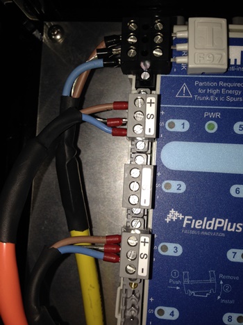
Because a Foundation fieldbus cable provides power to the instrument, the normal assumption is that it must follow the same practice as normal power wiring. Standard 120 Vac power has a hot (usually black or some other color), neutral (white) and ground (green or conduit) and everything needs to be properly grounded.
But Foundation fieldbus is first and foremost a communication medium, so a different rule applies: signal wires shall not be grounded. Unfortunately, what sometimes happens is the installer sees three conductors and terminates three conductors. The result is noise on the segment. Hopefully, the installer will know to check the number of Fieldbus terminators (more on that later). If that count is correct, a look at the terminal block will show that the shield is screwed down at the wrong termination. Shields should only be connected to a single point. Most installers now do this at the H1 host or power isolator interface end only.
2. Terminators
Since Foundation fieldbus is a bus system, terminators are placed at each end of the segment to avoid communication reflections which can add noise to the segment and inhibit communication. Technicians typically expect that two terminators on a segment, one near the H1 card and one on the last device on the segment, will solve the problem, but it doesn’t. There can be either too few or too many terminators on the segment, as sometimes one terminator can be too few while three may be too many.
Here’s what can happen: If the segment length is short, there is probably very little noise on the segment whether it has a terminator or not. This situation may have existed in the field for years. But when the day comes when more devices must be added, the decision to use a short segment because there is plenty of room seems perfectly sensible. So the trunk cable is extended from one junction box/tee to another and the overall segment length is increased. Bujt now noise shows up where it hadn’t before. Why?
The problem has to be solved through consistent use of terminators. The best approach isn’t always intuitive and vendors may not be able to help as something as simple as a terminator can vary from company to company. Manufacturer X uses a jumper, manufacturer Y uses a switch and manufacturer Z's product has to be mounted in a junction box.
Fortunately, this issue is becoming less of a problem as Foundation fieldbus ancillary product suppliers have offered more self-terminating junction boxes and power isolators. A wider range of devices is now available that avoids setting jumpers, selecting DIP switches or screwing down connectors in a termination device.
3. Power Supplies
Beware the temptation to use generic, non-Foundation fieldbus rated 24Vdc bulk power supplies, as Foundation fieldbus devices have stringent power requirements.
The Foundation fieldbus specification allows for 9 to 32Vdc power. Applying Ohm’s Law, voltage on a segment will dip slightly as each new device is added and consumes current. But that’s just milliamps and doesn’t affect the voltage too much. The voltage should still remain comfortably within the requirements, well above 9V, but there is more to it. Many factors affect voltage drop along the segment, so power isolators from many vendors are designed to ensure that power is maintained in the 19 to 28Vdc range with little variation regardless of the number of devices drawing current.

Suppliers are helping as many power isolators now provide segment diagnostics that can be sent to the host or asset management systems. Some can even determine where noise is originating down to individual devices, simplifying troubleshooting.
4. Stick with Tested and Registered Products
The Fieldbus Foundation has instituted a series of testing processes and procedures for devices, host systems and ancillary products to ensure interoperability among products from different suppliers. These tests go through regular reviews and revisions to help users ensure products from different suppliers will work with each other and the host. Suppliers also do their own internal testing with different devices and hosts to minimize risk during product development and to ensure interoperability.
While this sounds sensible, it has not always been the case, and problems may surface when using older devices. In the early days of Foundation fieldbus technology, suppliers often found areas where the specifications had to be interpreted. This caused some interoperability issues. Reviews and revisions over the years have eliminated most of these ambiguities. Foundation fieldbus ancillary products like power isolators, junction boxes, cables and terminators are also tested with the same test criteria and registered at the Foundation.
Coming in Part Two: Keeping device configuration and addressing clear.
http://insights.globalspec.com/article/126/10-steps-to-better-foundation-fieldbus-installations-part-1
No comments:
Post a Comment