Tuesday, November 25, 2014
Friday, November 21, 2014
Thursday, November 13, 2014
Wednesday, November 12, 2014
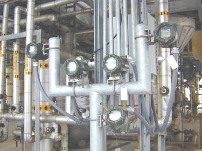
Characteristics of XLPE insulated cables with reference to the UK standards

Characteristics
of XLPE insulated cables with reference to the UK standards (on photo:
10kV Aluminium Conductor XLPE Insulated Aerial Cable)
Cross-linking effect
XLPE is the recognized abbreviation for cross-linked polyethylene. This and other cross-linked synthetic materials, of which EPR (ethylene propylene rubber) is a notable example, are being increasingly used as cable insulants for a wide range of voltages.Polyethylene has good electrical properties and in particular a low dielectric loss factor, which gives it potential for use at much higher voltages than PVC. Polyethylene has been and still is used as a cable insulant, but, as a thermoplastic material, its applications are limited by thermal constraints.
Cross-linking
is the effect produced in the vulcanization of rubber and for materials
like XLPE the cross-linking process is often described as ‘vulcan-
ization’ or ‘curing’. Small amounts of chemical additives to the polymer
enable the molecular chains to be cross-linked into a lattice formation
by appropriate treatment after extrusion.
The effect of the
cross-linking is to inhibit the movement of molecules with respect to
each other under the stimulation of heat and this gives the improved
stability at elevated temperatures compared with the thermoplastic
materials. This permits higher operating temperatures, both for normal
loading and under short-circuit conditions, so that an XLPE cable has a
higher current rating than its equivalent PVC counterpart.The effects of ageing, accelerated by increased temperature, also have to be taken into account, but in this respect also XLPE has favourable characteristics.BS 5467 specifies construction and requirements for XLPE and EPR-insulated wire-armoured cables for voltages up to 3.3kV. The construction is basically similar to that of PVC cables to BS 6346, except for the difference in insulant. Because of the increased toughness of XLPE the thicknesses of insulation are slightly reduced compared with PVC.

33kV XLPE cable (photo credit: openelectrical.org)
The standard also covers cables with HEPR (hard ethylene propylene rubber) insulation, but XLPE is the material most commonly used. From 3.8kV up to 33kV, XLPE and EPR insulated cables are covered by BS 6622 which specifies construction, dimensions and requirements.
The polymeric forms of cable insulation
are more susceptible to electrical discharge than impregnated paper and
at the higher voltages, where the electrical stresses are high enough
to promote discharge, it is important to minimize gaseous spaces within
the insulation or at its inner and outer surfaces.
To this end XLPE cables for 6.6 kV and above have semiconducting screens
over the conductor and over each insulated core. The conductor screen
is a thin layer extruded in the same operation as the insulation and
cross-linked with it so that the two components are closely bonded. The
screen over the core may be a similar extruded layer or a layer of
semiconducting paint with a semiconducting tape applied over it.Single-core and three-core designs are employed, and there is scope for constructional variation depending on the conditions of use, subject to the cores being surrounded individually or as a three-core assembly by a metallic layer, which may be an armour, sheath or copper wires or tapes.A typical armoured construction which has been supplied in substantial quantities is shown in Figure 1 below.

Figure 1 – XLPE cable construction
Where:
- Circular stranded conductor
- Semiconductor XLPE screen
- XLPE insulation
- Semiconducting tape screen
- Copper tape screen
- PVC filler
- Binder
- Extruded PVC sheath
- Galvanized steel wire armour 10. Extruded PVC oversheath

Underground direct buried power cables
For underground distribution at 11kV, the XLPE cable does not compete economically with the paper-insulated aluminium-sheathed cable, but work is in progress on standardizing and assessing XLPE cable design, including trial installations, in preparation for any change in the situation. Overseas, where circumstances are different, XLPE cable is the type in major demand.
With manufacturing facilities increasingly orientated to this market, XLPE insulated cables constitute a large proportion of UK production.
Tuesday, November 4, 2014
10 Steps to Better Foundation Fieldbus Installations—Part 2
Lessons learned from fieldbus users can help improve systems, performance and personnel. Part one of
this three part series discusses how wiring mistakes interfere with
communication. This installment examines how configuration and
addressing make all the difference. Part 3 addresses working in a
fieldbus environment and will be published in the near future.
Over years of visiting end user sites, talking to system integrators, and internal conversations with others within our own company, tribal knowledge begins to accumulate of what works, what doesn’t and what can be improved. When working in a Foundation fieldbus (FF) context, we find some user companies swear by the technology and won’t consider anything else, while others cannot claim such positive experiences.
When considering what differentiates enthusiastic users from those who gave up, many of the same top 10 points emerge. This series of articles provides details for each point. Here are the Top 10, plus one. (Items 1-4 are discussed here.)
1. Wiring practice pitfalls
2. Terminators
3. Power supplies
4. Stick with tested and registered products
5. Incorrect DD/CFF fles
6. Using the link active scheduler
7. Device addressing
8. Choosing between publisher-subscriber and client-server communication
9. Traditional project management techniques may not apply
10. Mismatch of work processes
11. Misunderstanding the value proposition
This means that when the device is added to a segment, the host automatically reads and performs some configurations to itself and/or the device to communicate correctly. In some cases, the host can self-generate a CFF by reading it from the device.
DD revision management is another issue addressed by automatically reading DD information from each device and keeping this information current on the host control system or asset management system. This functionality is often supported by the supplier via a software upgrade, but it may require manual effort.
LAS functionality can reside in any one of the devices on a segment with link master capability. The scheduled communication cycle to run all the function blocks in all the devices on the segment is known as the segment’s macrocycle, which is the base time (0.5, 1 and 2 seconds are used most commonly) for scheduled communication.
As the number of devices and function blocks to be executed on the segment grows, so will the minimum macrocycle time. The time left over after deterministic communication is made available for responding to other types of requests for information from FF devices, such as diagnostic information or other messages.
Generally, the host system H1 module is automatically configured as the primary LAS. There may be a redundant module in the system that serves as the backup LAS, which works well when LAS redundancy on the H1 I/O modules is desirable. But what is the actual requirement for configuring a backup LAS? If it’s desirable that the segment should keep running despite loss of communication from the host system, then the LAS function needs to reside in one of the devices on the segment.
In some implementations, host redundancy is all that is necessary, as depending upon the configuration of the power and power isolator, a loss of an H1 I/O card will result in a loss of the host’s view of the process, rendering irrelevant LAS redundancy via a device.
Another requirement is power redundancy for a bulk power supply and power isolators. If power to the entire segment is lost, then the location of the LAS function doesn’t matter. However, if the configuration is such that the backup LAS can function without the main power supply because it has its own backup source of power, then that device needs LAS capabilities. Some vendors offer LAS capability within a device for an extra cost, so it’s important only to specify this feature as needed.
Rules for backup LAS in the Foundation fieldbus specification call for the lowest address on the segment to claim LAS first. Upon failure of that device, the next lowest address takes over and so on. Thus, most implementations make the host redundant H1 module the lowest address on the segment.
But, is a third backup configured in a device in addition to the host backup? In practice this is rarely done, either due to an unwillingness to buy such functionality in the device, or by not activating and providing a suitable address when putting the device on the segment. This is often a simple feature to implement and it ensures execution of devices on a segment without the host, and should thus be configured where applicable. Also, if control functionality is being run in a host system, then running a backup LAS in field device is useless.
Many devices come from the factory with a default address. A technician may install the device on the segment without checking the address and then have to figure out why it doesn’t show up on the live list.
He or she often assumes the device is inoperable and uses a bench tool, such as a laptop with Foundation fieldbus interface card or handheld communicator, to scan the segment. Suddenly, the supposedly inoperative device shows up because that tool scans the entire range. This may prompt the technician to check the scan range of the host.
Host systems should generally be configured to access all the variables required for real-time control and display via publisher-subscriber to guarantee update time. Additional data and diagnostic information can then be accessed via client-server on an as-needed basis.
http://insights.globalspec.com/article/171/10-steps-to-better-foundation-fieldbus-installations-part-2
Over years of visiting end user sites, talking to system integrators, and internal conversations with others within our own company, tribal knowledge begins to accumulate of what works, what doesn’t and what can be improved. When working in a Foundation fieldbus (FF) context, we find some user companies swear by the technology and won’t consider anything else, while others cannot claim such positive experiences.
When considering what differentiates enthusiastic users from those who gave up, many of the same top 10 points emerge. This series of articles provides details for each point. Here are the Top 10, plus one. (Items 1-4 are discussed here.)
1. Wiring practice pitfalls
2. Terminators
3. Power supplies
4. Stick with tested and registered products
5. Incorrect DD/CFF fles
6. Using the link active scheduler
7. Device addressing
8. Choosing between publisher-subscriber and client-server communication
9. Traditional project management techniques may not apply
10. Mismatch of work processes
11. Misunderstanding the value proposition
5. Incorrect DD/CFF Files
Let’s say you have a malfunctioning pressure sensor and you decide to replace it with an older unit from inventory. Unfortunately, you discover that it has an older device description (DD) or capabilities file, also known as a common file format (CFF) file. (It’s worth noting that he device descriptor (DD) file allows operation of devices from different suppliers on the same fieldbus with single host system. The common file format (CFF) is an ASCII file which describes the functions and capabilities of a field device. The CFF file is used in conjunction with the DD file to enable a host system to configure the system off-line.) Conversely, you may want to replace an older unit with a newer model with a new DD of CFF file. Either scenario can cause problems, because if the files are different in the host system and the device, then the device will not commission or communicate.
Fortunately,
this legacy problem is being addressed and is disappearing. Suppliers
are tackling this issue by reading DD/CFF files from devices connected
to the host and self-selecting the correct files for the device during
commissioning. This allows for more plug-and-play functionality.
This means that when the device is added to a segment, the host automatically reads and performs some configurations to itself and/or the device to communicate correctly. In some cases, the host can self-generate a CFF by reading it from the device.
DD revision management is another issue addressed by automatically reading DD information from each device and keeping this information current on the host control system or asset management system. This functionality is often supported by the supplier via a software upgrade, but it may require manual effort.
6. Using the Backup Link Active Scheduler
The backup link active scheduler (LAS) is one of the unique capabilities of Foundation fieldbus, but it isn’t used as widely as one might expect. It manages data traffic control to achieve scheduled communication on the segment and it can keep the segment working even when the host system has failed.LAS functionality can reside in any one of the devices on a segment with link master capability. The scheduled communication cycle to run all the function blocks in all the devices on the segment is known as the segment’s macrocycle, which is the base time (0.5, 1 and 2 seconds are used most commonly) for scheduled communication.
As the number of devices and function blocks to be executed on the segment grows, so will the minimum macrocycle time. The time left over after deterministic communication is made available for responding to other types of requests for information from FF devices, such as diagnostic information or other messages.
Generally, the host system H1 module is automatically configured as the primary LAS. There may be a redundant module in the system that serves as the backup LAS, which works well when LAS redundancy on the H1 I/O modules is desirable. But what is the actual requirement for configuring a backup LAS? If it’s desirable that the segment should keep running despite loss of communication from the host system, then the LAS function needs to reside in one of the devices on the segment.
In some implementations, host redundancy is all that is necessary, as depending upon the configuration of the power and power isolator, a loss of an H1 I/O card will result in a loss of the host’s view of the process, rendering irrelevant LAS redundancy via a device.
Another requirement is power redundancy for a bulk power supply and power isolators. If power to the entire segment is lost, then the location of the LAS function doesn’t matter. However, if the configuration is such that the backup LAS can function without the main power supply because it has its own backup source of power, then that device needs LAS capabilities. Some vendors offer LAS capability within a device for an extra cost, so it’s important only to specify this feature as needed.
Rules for backup LAS in the Foundation fieldbus specification call for the lowest address on the segment to claim LAS first. Upon failure of that device, the next lowest address takes over and so on. Thus, most implementations make the host redundant H1 module the lowest address on the segment.
But, is a third backup configured in a device in addition to the host backup? In practice this is rarely done, either due to an unwillingness to buy such functionality in the device, or by not activating and providing a suitable address when putting the device on the segment. This is often a simple feature to implement and it ensures execution of devices on a segment without the host, and should thus be configured where applicable. Also, if control functionality is being run in a host system, then running a backup LAS in field device is useless.
7. Device Addressing
Are all the addresses for devices on a segment in the range that the system is scanning? Some systems scan a finite range in the link-master address range from 20-32 (0x14-0x20) and then at the basic address range 232-248 (0xE8 - 0xF7). This is done to increase performance for sink/source event reporting, and for on-demand communication of parameters to entities such as asset management systems. Knowing this can reduce the chore of finding why some devices don’t appear on the live list, which is the list of devices that reply to the host’s request as being on the segment.Many devices come from the factory with a default address. A technician may install the device on the segment without checking the address and then have to figure out why it doesn’t show up on the live list.
He or she often assumes the device is inoperable and uses a bench tool, such as a laptop with Foundation fieldbus interface card or handheld communicator, to scan the segment. Suddenly, the supposedly inoperative device shows up because that tool scans the entire range. This may prompt the technician to check the scan range of the host.
8. Choosing Between Publisher-Subscriber and Client-Server Communication
Foundation fieldbus supports publisher-subscriber and client-server communication. Some devices have multiple variables available and should use publisher-subscriber for the primary variable and client-server for any other information. This is done to reduce scheduled communication time for the segment since the other information may only be needed upon request and not need to be executed every macrocycle.Host systems should generally be configured to access all the variables required for real-time control and display via publisher-subscriber to guarantee update time. Additional data and diagnostic information can then be accessed via client-server on an as-needed basis.
http://insights.globalspec.com/article/171/10-steps-to-better-foundation-fieldbus-installations-part-2
10 Steps to Better Foundation Fieldbus Installations—Part 1
Lessons learned from fieldbus users can help improve your
systems, performance and personnel. Part one: How wiring mistakes
interfere with communication.
Over years of visiting end-user sites, talking to system integrators and internal conversations with others within our own company, tribal knowledge begins to accumulate of what works, what doesn’t and what can be improved. When working in a Foundation fieldbus (FF) context, we find some user companies swear by the technology and won’t consider anything else, while others cannot claim such positive experiences.
When considering what differentiates enthusiastic users from those who gave up, many of the same top 10 points emerge. Some of the points are specific to Foundation fieldbus and others are more universal, so even if you aren’t a Foundation fieldbus user you might find some familiar topics addressed. Here are the Top 10, plus one:
1. Wiring practice pitfalls
2. Terminators
3. Power supplies
4. Stick with tested and registered products
5. Incorrect DD/CFF files
6. Using the link active scheduler
7. Device addressing
8. Choosing between publisher-subscriber and client-server communication
9. Traditional Project Management Techniques May Not Apply
10. Mismatch of work processes
11. Misunderstanding the value proposition
The first four points are covered in this article. The remaining points are covered in Parts 2 and 3, which will publish soon.
1. Wiring Practice Pitfalls
Good wiring practices apply to all sorts of field devices, but are particularly important with Foundation fieldbus because the digital communication running through the cables is sensitive to electrical noise. Terminations need to be executed properly and Foundation fieldbus cabling should be installed in appropriate cable trays or conduit just like any other field device wiring. So why is this a potential problem area?
Many companies have encountered issues with simple termination and routing rules. In one instance we found high-voltage cables in the same trays with cables from process sensors and actuators. As a result, individual field devices might fall off a segment for a period of time and then mysteriously reappear.
Basic troubleshooting may show a correlation between operating a specific piece of equipment, say a pump controlled by a variable frequency drive (VFD), and device segment drop-offs. If the cables to the VFD are too close to the Foundation fieldbus cables, electrical noise generated by the VFD can disrupt the digital signal. Putting an oscilloscope on the segment can prove the point by showing the offending electrical noise and consequent distorted waveforms.
Other wiring pitfalls relate to device connections. Although many field devices are insensitive to polarity, others are not. As a result, technicians need to pay particular attention.
Here’s a quick quiz: Most Foundation fieldbus cables are brown, blue and green colored wire coverings. Which wire should be positive, the brown wire or the blue one? How is it connected at the H1 module or power isolator?
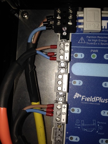
Trying to figure it out by
intuition is a good way to get into trouble. Perhaps you say to
yourself: “Brown represents earth or ground and is therefore negative.
That means blue is for the sky and positive.” There is a certain logic
to that idea but it’s wrong. With Foundation fieldbus, brown is positive
and blue is negative, which provides a guide for hooking up
transmitters, positioners and H1 interfaces. However, the key is
consistency when it comes to which wire is connected to which pole.
Device manufacturers may not help much. Some terminal blocks are more
clearly marked than others. Just because polarity is not obvious does
not mean the device is not sensitive to polarity. To complicate matters
further, Foundation fieldbus cable has three conductors: blue, brown and
a shield, often green or striped green. A given device may also have
three terminals.
Because a Foundation fieldbus cable provides power to the instrument, the normal assumption is that it must follow the same practice as normal power wiring. Standard 120 Vac power has a hot (usually black or some other color), neutral (white) and ground (green or conduit) and everything needs to be properly grounded.
But Foundation fieldbus is first and foremost a communication medium, so a different rule applies: signal wires shall not be grounded. Unfortunately, what sometimes happens is the installer sees three conductors and terminates three conductors. The result is noise on the segment. Hopefully, the installer will know to check the number of Fieldbus terminators (more on that later). If that count is correct, a look at the terminal block will show that the shield is screwed down at the wrong termination. Shields should only be connected to a single point. Most installers now do this at the H1 host or power isolator interface end only.
2. Terminators
Since Foundation fieldbus is a bus system, terminators are placed at each end of the segment to avoid communication reflections which can add noise to the segment and inhibit communication. Technicians typically expect that two terminators on a segment, one near the H1 card and one on the last device on the segment, will solve the problem, but it doesn’t. There can be either too few or too many terminators on the segment, as sometimes one terminator can be too few while three may be too many.
Here’s what can happen: If the segment length is short, there is probably very little noise on the segment whether it has a terminator or not. This situation may have existed in the field for years. But when the day comes when more devices must be added, the decision to use a short segment because there is plenty of room seems perfectly sensible. So the trunk cable is extended from one junction box/tee to another and the overall segment length is increased. Bujt now noise shows up where it hadn’t before. Why?
The problem has to be solved through consistent use of terminators. The best approach isn’t always intuitive and vendors may not be able to help as something as simple as a terminator can vary from company to company. Manufacturer X uses a jumper, manufacturer Y uses a switch and manufacturer Z's product has to be mounted in a junction box.
Fortunately, this issue is becoming less of a problem as Foundation fieldbus ancillary product suppliers have offered more self-terminating junction boxes and power isolators. A wider range of devices is now available that avoids setting jumpers, selecting DIP switches or screwing down connectors in a termination device.
3. Power Supplies
Beware the temptation to use generic, non-Foundation fieldbus rated 24Vdc bulk power supplies, as Foundation fieldbus devices have stringent power requirements.
The Foundation fieldbus specification allows for 9 to 32Vdc power. Applying Ohm’s Law, voltage on a segment will dip slightly as each new device is added and consumes current. But that’s just milliamps and doesn’t affect the voltage too much. The voltage should still remain comfortably within the requirements, well above 9V, but there is more to it. Many factors affect voltage drop along the segment, so power isolators from many vendors are designed to ensure that power is maintained in the 19 to 28Vdc range with little variation regardless of the number of devices drawing current.

That
opens a new set of questions: What capacity (amperage rating) power
supply is needed? Should it be redundant? Should the power isolator be
redundant? Must there be one power supply per segment or is it
appropriate to use a single large unit to power multiple segments?
Again, there are no simple answers, but many guidelines for segment
design are available to deal with voltage and current consumption in
order to answer these questions.
Suppliers are helping as many power isolators now provide segment diagnostics that can be sent to the host or asset management systems. Some can even determine where noise is originating down to individual devices, simplifying troubleshooting.
4. Stick with Tested and Registered Products
The Fieldbus Foundation has instituted a series of testing processes and procedures for devices, host systems and ancillary products to ensure interoperability among products from different suppliers. These tests go through regular reviews and revisions to help users ensure products from different suppliers will work with each other and the host. Suppliers also do their own internal testing with different devices and hosts to minimize risk during product development and to ensure interoperability.
While this sounds sensible, it has not always been the case, and problems may surface when using older devices. In the early days of Foundation fieldbus technology, suppliers often found areas where the specifications had to be interpreted. This caused some interoperability issues. Reviews and revisions over the years have eliminated most of these ambiguities. Foundation fieldbus ancillary products like power isolators, junction boxes, cables and terminators are also tested with the same test criteria and registered at the Foundation.
Coming in Part Two: Keeping device configuration and addressing clear.
http://insights.globalspec.com/article/126/10-steps-to-better-foundation-fieldbus-installations-part-1
Over years of visiting end-user sites, talking to system integrators and internal conversations with others within our own company, tribal knowledge begins to accumulate of what works, what doesn’t and what can be improved. When working in a Foundation fieldbus (FF) context, we find some user companies swear by the technology and won’t consider anything else, while others cannot claim such positive experiences.
When considering what differentiates enthusiastic users from those who gave up, many of the same top 10 points emerge. Some of the points are specific to Foundation fieldbus and others are more universal, so even if you aren’t a Foundation fieldbus user you might find some familiar topics addressed. Here are the Top 10, plus one:
1. Wiring practice pitfalls
2. Terminators
3. Power supplies
4. Stick with tested and registered products
5. Incorrect DD/CFF files
6. Using the link active scheduler
7. Device addressing
8. Choosing between publisher-subscriber and client-server communication
9. Traditional Project Management Techniques May Not Apply
10. Mismatch of work processes
11. Misunderstanding the value proposition
The first four points are covered in this article. The remaining points are covered in Parts 2 and 3, which will publish soon.
1. Wiring Practice Pitfalls
Good wiring practices apply to all sorts of field devices, but are particularly important with Foundation fieldbus because the digital communication running through the cables is sensitive to electrical noise. Terminations need to be executed properly and Foundation fieldbus cabling should be installed in appropriate cable trays or conduit just like any other field device wiring. So why is this a potential problem area?
Many companies have encountered issues with simple termination and routing rules. In one instance we found high-voltage cables in the same trays with cables from process sensors and actuators. As a result, individual field devices might fall off a segment for a period of time and then mysteriously reappear.
Basic troubleshooting may show a correlation between operating a specific piece of equipment, say a pump controlled by a variable frequency drive (VFD), and device segment drop-offs. If the cables to the VFD are too close to the Foundation fieldbus cables, electrical noise generated by the VFD can disrupt the digital signal. Putting an oscilloscope on the segment can prove the point by showing the offending electrical noise and consequent distorted waveforms.
Other wiring pitfalls relate to device connections. Although many field devices are insensitive to polarity, others are not. As a result, technicians need to pay particular attention.
Here’s a quick quiz: Most Foundation fieldbus cables are brown, blue and green colored wire coverings. Which wire should be positive, the brown wire or the blue one? How is it connected at the H1 module or power isolator?
Because a Foundation fieldbus cable provides power to the instrument, the normal assumption is that it must follow the same practice as normal power wiring. Standard 120 Vac power has a hot (usually black or some other color), neutral (white) and ground (green or conduit) and everything needs to be properly grounded.
But Foundation fieldbus is first and foremost a communication medium, so a different rule applies: signal wires shall not be grounded. Unfortunately, what sometimes happens is the installer sees three conductors and terminates three conductors. The result is noise on the segment. Hopefully, the installer will know to check the number of Fieldbus terminators (more on that later). If that count is correct, a look at the terminal block will show that the shield is screwed down at the wrong termination. Shields should only be connected to a single point. Most installers now do this at the H1 host or power isolator interface end only.
2. Terminators
Since Foundation fieldbus is a bus system, terminators are placed at each end of the segment to avoid communication reflections which can add noise to the segment and inhibit communication. Technicians typically expect that two terminators on a segment, one near the H1 card and one on the last device on the segment, will solve the problem, but it doesn’t. There can be either too few or too many terminators on the segment, as sometimes one terminator can be too few while three may be too many.
Here’s what can happen: If the segment length is short, there is probably very little noise on the segment whether it has a terminator or not. This situation may have existed in the field for years. But when the day comes when more devices must be added, the decision to use a short segment because there is plenty of room seems perfectly sensible. So the trunk cable is extended from one junction box/tee to another and the overall segment length is increased. Bujt now noise shows up where it hadn’t before. Why?
The problem has to be solved through consistent use of terminators. The best approach isn’t always intuitive and vendors may not be able to help as something as simple as a terminator can vary from company to company. Manufacturer X uses a jumper, manufacturer Y uses a switch and manufacturer Z's product has to be mounted in a junction box.
Fortunately, this issue is becoming less of a problem as Foundation fieldbus ancillary product suppliers have offered more self-terminating junction boxes and power isolators. A wider range of devices is now available that avoids setting jumpers, selecting DIP switches or screwing down connectors in a termination device.
3. Power Supplies
Beware the temptation to use generic, non-Foundation fieldbus rated 24Vdc bulk power supplies, as Foundation fieldbus devices have stringent power requirements.
The Foundation fieldbus specification allows for 9 to 32Vdc power. Applying Ohm’s Law, voltage on a segment will dip slightly as each new device is added and consumes current. But that’s just milliamps and doesn’t affect the voltage too much. The voltage should still remain comfortably within the requirements, well above 9V, but there is more to it. Many factors affect voltage drop along the segment, so power isolators from many vendors are designed to ensure that power is maintained in the 19 to 28Vdc range with little variation regardless of the number of devices drawing current.
Suppliers are helping as many power isolators now provide segment diagnostics that can be sent to the host or asset management systems. Some can even determine where noise is originating down to individual devices, simplifying troubleshooting.
4. Stick with Tested and Registered Products
The Fieldbus Foundation has instituted a series of testing processes and procedures for devices, host systems and ancillary products to ensure interoperability among products from different suppliers. These tests go through regular reviews and revisions to help users ensure products from different suppliers will work with each other and the host. Suppliers also do their own internal testing with different devices and hosts to minimize risk during product development and to ensure interoperability.
While this sounds sensible, it has not always been the case, and problems may surface when using older devices. In the early days of Foundation fieldbus technology, suppliers often found areas where the specifications had to be interpreted. This caused some interoperability issues. Reviews and revisions over the years have eliminated most of these ambiguities. Foundation fieldbus ancillary products like power isolators, junction boxes, cables and terminators are also tested with the same test criteria and registered at the Foundation.
Coming in Part Two: Keeping device configuration and addressing clear.
http://insights.globalspec.com/article/126/10-steps-to-better-foundation-fieldbus-installations-part-1
Subscribe to:
Posts (Atom)