Showing posts with label conductor. Show all posts

Monday, January 30, 2017

4 Practical Approaches To Minimize Voltage Drop Problems

What NEC states for max. voltage drop?

The NEC states in an Informational Note that a maximum voltage drop of 3% for branch circuit conductors, and 5% for feeder and branch circuit conductors together, will provide reasonable efficiency of operation for general use circuits.
For sensitive electronic loads, circuits should be designed for a maximum of 1.5% voltage drop for branch circuits at full load, and 2.5% voltage drop for feeder and branch circuits combined at full load.

1. Increase the Number or Size of Conductors

Parallel or oversized conductors have lower resistance per unit length than the Code-required minimum-sized conductors, reducing voltage drop and increasing energy efficiency with lower losses than using the Code-required minimum-sized conductor.
In data centers and other sensitive installations, it is not uncommon to find conductor gauges for phase, neutral, and ground exceeding Code minimums, and a separate branch circuit installed for each large or sensitive load.
To limit neutral-to-ground voltage drop, install a separate, full-sized neutral conductor for each phase conductor in single-phase branch circuit applications.
For three-phase feeder circuits, do not downsize the grounded conductor or neutral. For three-phase circuits where significant non-linear loads are anticipated, it is recommended to install grounded or neutral conductors with at least double the ampacity of each phase conductor.

2. Decrease Load Current

Limiting the amount of equipment that can be connected to a single circuit will limit the load current on the circuit. Limit the number of receptacles on each branch circuit to three to six.
Install individual branch circuits to sensitive electronic loads or loads with a high inrush current.
For residential applications, install outdoor receptacles not to exceed 50 linear feet between receptacles, with a minimum of one outdoor receptacle on each side of the house, and with individual branch circuits with a minimum of 12 AWG to each receptacle.


3. Decrease Conductor Length

Decreasing conductor length reduces the resistance of the conductor, which reduces voltage drop. Circuit lengths are usually fixed, but some control can be exercised at the design stage if panels or subpanels are located as close as possible to the loads, especially for sensitive electronic equipment.


Click here to access the full article

Tuesday, November 1, 2016

Sizing of power cables for circuit breaker controlled feeders (part 3)


3. Criteria Starting and running voltage drops in cable

This criterion is applied so that the cross sectional area of the cable is sufficient to keep the voltage drop (due to impedance of cable conductor) within the specified limit so that the equipment which is being supplied power through that cable gets at least the minimum required voltage at its power supply input terminal during starting and running condition both.

Cables shall be sized so that the maximum voltage drop between the supply source and the load when carrying the design current does not exceed that which will ensure safe and efficient operation of the associated equipment. It is a requirement that the voltage at the equipment is greater than the lowest operating voltage specified for the equipment in the relevant equipment standard.
So before starting with calculation for voltage drop let us first analyze that what is the permissible voltage drop as per relevant standards and guidelines and what is the possible logic behind selecting these values as the permissible values.

Indian standard 1255- CODE OF PRACTICE FOR INSTALLATION AND MAINTENANCE OF POWER CABLES UP TO AND INCLUDING 33 kV RATING in its clause 4.2.3.4 mentions the permissible value for different cross sectional sizes of Aluminium conductor in volts/kM/Ampere for cables from voltage grade of 1.1kV till 33kV. Since we calculate voltage drop in terms of percentage of source voltage, this clause is not very widely used in basic as well as detailed engineering fraternity.
Its complex unit requires to be multiplied by cable length and ampacity. However one can definitely check for any cable size and length, what value is obtained in terms of percentage?

IEEE standard 525 – Guide for the Design and Installation of Cable Systems in Substations in its annexure C, clause number C3 mentions that Voltage drop is commonly expressed as a percentage of the source voltage. An acceptable voltage drop is determined based on an overall knowledge of the system. Typical limits are 3% from source to load center, 3% from load center to load, and 5% total from source to load. These values are indicated diagrammatically below.

6.6kV substation layout


Click here to access the full article

Sizing of power cables for circuit breaker controlled feeders (part 2)

2. Criteria-2 Continuous current capacity (Ampacity)

This criterion is applied so that cross section of the cable can carry the required load current continuously at the designed ambient temperature and laying condition. Ampacity is defined as the current in amperes a conductor can carry continuously under the conditions of surrounding medium in which the cables are installed. An ampacity study is the calculation of the temperature rise of the conductor in a cable system under steady-state conditions.
Cable ampacity, if required to be calculated than it is calculated as per the following equation givenin IEEE -399, section 13.


This equation is based on Neher-McGrath method where,
  • Tc’ – allowable conductor temperature (ºC)
  • Ta’ – ambient temperature (either soil or air) (ºC)
  • ∆Td – temperature rise of conductor due to dielectric heating (ºC)
  • ∆Tint – temperature rise of the conductor due to interference heating from adjacent cables (ºC)
  • Rac – electrical ac resistance of conductor including skin effect, proximity and temperature effects (µ_/ft)
  • R’ca – effective total thermal resistance of path between conductor and surrounding ambient to include the effects of load factor, shield/sheath losses, metallic conduit losses, effects of multiple conductors in the same duct etc (thermal- Ωft, ºC-cm/W).
From the above equation it is clear that the rated current carrying capacity of a conductor is dependent on the following factors:
  1. Ambient temperature (air or ground)
  2. Grouping and proximity to other loaded cables, heat sources etc.
  3. Method of installation (above ground or below ground)
  4. Thermal conductivity of the medium in which the cable is installed
  5. Thermal conductivity of the cable constituents
However please note that while sizing a power cable we never calculate the ampacity. The above equation is used to analyze the cable ampacities of unique installations. Standard ampacity tables are available for a variety of cable types and cable installation methods and can be used for determining the current carrying capacity of a cable for a particular application.

These standards provide tabulated ampacity data in manufacturers catalog for cables installed in air, in duct bank,  directly buried or in trays for a particular set of conditions clearly defined.
It is because of this reason that we need to give the reference of manufacturers catalog from where the ampacity  values are picked up.

Now once the current carrying capacity of a cable is found from standard catalog; we convert that rated capacity (Ampacity) into actual laying condition. The standard current ratings for cables are modified by the application of suitable multiplying factors to account for the actual installation conditions. Hence we define one more term here called ampacity deration factor.

Ampacity duration factor is defined as the product of various factors which accounts for the fraction decrease in the ampacity of the conductor. Those factors and physical condition deriving them are as follows:
  1. K1= Variation in ambient air temperature for cables laid in air / ground temperature for cables laid underground.
  2. K2 = Cable laying arrangement.
  3. K3 = Depth of laying for cables laid direct in ground.
  4. K4 = Variation in thermal resistivity of soil.
Ampacity Deration factor = Product of applicable multiplying factors among 1 to 4 listed above.
K = K1 x K2 x K3 x K4

Now from where do we get these multiplying factors to find the overall ampacity deration factor? Againwe get these values from manufacturers catalog because manufacturer of the cable is in best position to conduct thepractical experiments and test on the cables and find the percentage/fractional decrease in current carrying capacity of the cable in various conditions.

For better understanding of the ampacity deration factor the following pictorial representation is provided below.

Table for ampacity deration factor along with pictorial representation is provided below.
However readers to note that ampacity deration factor table provided in this article is to verified from the manufacturers catalog which is intended to be used for project.


Click here to access the full article


Monday, June 13, 2016

What Would Be The Best Conductor Material for Electrical Cables

Al or Cu conductor…

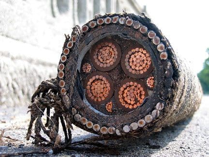
The conductivity of copper is 65% higher than that of aluminium which means that the conductor size of similarly rated cables is proportionately smaller. Correspondingly less expense is then incurred in providing for insulation, shielding and armouring the cables themselves. Transport of the less-bulky cables is easier and so is installation. In limited spaces in cable ducts, the smaller volume and better ductility of copper cables can have an even larger benefit.
Copper cables are easily jointed because copper does not form on its surface a tough, non-conducting oxide. The oxide film that does form is thin, strongly adherent and electrically conductive, causing few problems.
Cleaning and protection of copper is easy and if joints are made as recommended they will not deteriorate to any great extent with age, which saves on maintenance costs.
HV copper cable
HV copper cable (photo credit: businessinsider.com)

For the same nominal current rating, the cable with the aluminum conductor is significantly larger in diameter, carries a proportionally greater volume of insulation and is not so easily installed because of being less flexible. Aluminum is notoriously difficult to joint reliably. Table 1 compares aluminum and copper conductors for equivalent current rating.

Table 1 – Comparison between Copper and Aluminum Conductors in XLPE Insulated Steel- Wire Armoured Cables.
CharacteristicCopper 300 m2Aluminum 500 m
Overall diameter (mm)66.583.9
Minimum bending radius (mm)550700
Max DC resistance/km at 20o C (ohm)0.06010.0617
Approx. voltage drop/A/m (mV)0.1900.188
Continuous current rating, drawn in to duct (amp)496501
(Cable: to BS 5467 (& IEC 502) 4-core, stranded conductors, XLPE insulation, PVC bedding, steel wire armour, PVC oversheath, rated at 0.6/1.0 kV)

These notes have largely been derived from reference to BS 7450 which is identical to IEC 1059. Both of these give full details of the variables to be considered and the ways in which optimum cable size determinations can be made.


Click here to access the full article


Tuesday, April 12, 2016

What Would Be The Best Conductor Material for Electrical Cables


HV copper cable (photo credit: businessinsider.com)

Al or Cu conductor…


What Would Be The Best Conductor Material for Electrical CablesThe conductivity of copper is 65% higher than that of aluminium which means that the conductor size of similarly rated cables is proportionately smaller. Correspondingly less expense is then incurred in providing for insulation, shielding and armouring the cables themselves. Transport of the less-bulky cables is easier and so is installation. In limited spaces in cable ducts, the smaller volume and better ductility of copper cables can have an even larger benefit.
Copper cables are easily jointed because copper does not form on its surface a tough, non-conducting oxide. The oxide film that does form is thin, strongly adherent and electrically conductive, causing few problems.


Cleaning and protection of copper is easy and if joints are made as recommended they will not deteriorate to any great extent with age, which saves on maintenance costs.

HV copper cableFor the same nominal current rating, the cable with the aluminium conductor is significantly larger in diameter, carries a proportionally greater volume of insulation and is not so easily installed because of being less flexible. Aluminium is notoriously difficult to joint reliably. Table 1 compares aluminium and copper conductors for equivalent current rating.


Table 1 – Comparison between Copper and Aluminium Conductors in XLPE Insulated Steel- Wire Armoured Cables.
 
Characteristic Copper 300 m2 Aluminium 500 m
Overall diameter (mm) 66.5 83.9
Minimum bending radius (mm) 550 700
Max DC resistance/km at 20o C (ohm) 0.0601 0.0617
Approx. voltage drop/A/m (mV) 0.190 0.188
Continuous current rating, drawn in to duct (amp) 496 501

(Cable: to BS 5467 (& IEC 502) 4-core, stranded conductors, XLPE insulation, PVC bedding, steel wire armour, PVC oversheath, rated at 0.6/1.0 kV)


These notes have largely been derived from reference to BS 7450 which is identical to IEC 1059. Both of these give full details of the variables to be considered and the ways in which optimum cable size determinations can be made.

Click here to access the full article

Thursday, March 31, 2016

4 Practical Approaches To Minimize Voltage Drop Problems

What NEC states for max. voltage drop?

The NEC states in an Informational Note that a maximum voltage drop of 3% for branch circuit conductors, and 5% for feeder and branch circuit conductors together, will provide reasonable efficiency of operation for general use circuits.
4 Practical Approaches To Minimize Voltage Drop ProblemsFor sensitive electronic loads, circuits should be designed for a maximum of 1.5% voltage drop for branch circuits at full load, and 2.5% voltage drop for feeder and branch circuits combined at full load.


1. Increase the Number or Size of Conductors

Parallel or oversized conductors have lower resistance per unit length than the Code-required minimum-sized conductors, reducing voltage drop and increasing energy efficiency with lower losses than using the Code-required minimum-sized conductor.
In data centers and other sensitive installations, it is not uncommon to find conductor gauges for phase, neutral, and ground exceeding Code minimums, and a separate branch circuit installed for each large or sensitive load.
To limit neutral-to-ground voltage drop, install a separate, full-sized neutral conductor for each phase conductor in single-phase branch circuit applications.
For three-phase feeder circuits, do not downsize the grounded conductor or neutral. For three-phase circuits where significant non-linear loads are anticipated, it is recommended to install grounded or neutral conductors with at least double the ampacity of each phase conductor.

2. Decrease Load Current

Limiting the amount of equipment that can be connected to a single circuit will limit the load current on the circuit. Limit the number of receptacles on each branch circuit to three to six.
Install individual branch circuits to sensitive electronic loads or loads with a high inrush current.
For residential applications, install outdoor receptacles not to exceed 50 linear feet between receptacles, with a minimum of one outdoor receptacle on each side of the house, and with individual branch circuits with a minimum of 12 AWG to each receptacle.


Click here to access the full article