Showing posts with label cable grounding. Show all posts

Wednesday, September 28, 2016

Practices for grounding and bonding of cable trays

Metallic Cable Trays

Cable tray may be used as the Equipment Grounding Conductor (EGC) in any installation where qualified persons will service the installed cable tray system. There is no restriction as to where the cable tray system is installed. The metal in cable trays may be used as the EGC as per the limitations of table 392.60(A).
All metallic cable trays shall be grounded as required in Article 250.96 regardless of whether or not the cable tray is being used as an equipment grounding conductor (EGC).
The EGC is the most important conductor in an electrical system as its function is electrical safety.

Grounding and bonding of cable trays


There are three wiring options for providing an EGC in a cable tray wiring system:
  1. An EGC conductor in or on the cable tray.
  2. Each multi-conductor cable with its individual EGC conductor.
  3. The cable tray itself is used as the EGC in qualifying facilities.

Correct bonding practices

To assure that the cable tray system is properly grounded

If an EGC cable is installed in or on a cable tray, it should be bonded to each or alternate cable tray sections via grounding clamps (this is not required by the NEC® but it is a desirable practice)
In addition to providing an electrical connection between the cable tray sections and the EGC, the grounding clamp mechanically anchors the EGC to the cable tray so that under fault current conditions the magnetic forces do not throw the EGC out of the cable tray.
A bare copper equipment grounding conductor should not be placed in an aluminum cable tray due to the potential for electrolytic corrosion of the aluminum cable tray in a moist environment.
For such installations, it is best to use an insulated conductor and to remove the insulation where bonding connections are made to the cable tray, raceways, equipment enclosures, etc. with tin or zinc plated connectors.

Click here to access the full article

Monday, January 18, 2016

Grounding and bounding for electrical systems

Why is Good Grounding Important?

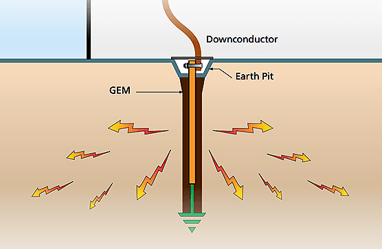
The transient nature of lightning with its associated fast rise times and large magnitude currents mean that special consideration needs to be given to grounding, for lightning protection to be effective.
Grounding and Bonding For Electrical SystemsMany factors such as soil resistivity variations, installation accessibility, layout and existing physical features are all site specific and tend to affect decisions on earthing methods employed.
The primary aim of a direct strike grounding system is to efficiently dissipate lightning energy into the ground and to help protect equipment and personnel.

Earthing Principles

A typical grounding systemLow impedance is the key to lightning protection. All earthing connections should be as short and direct as possible to minimize inductance and reduce peak voltages induced in the connections. The ground electrode system must efficiently couple lightning surges into the ground by maximizing capacitive coupling to the soil.
The resistance of the ground itself to lightning currents must also be minimized. Only when all these factors are taken into account will maximum lightning protection be achieved.


Ground Impedance

Soil resistivity is an important design consideration. It varies markedly for different soil types, moisture content and temperatures and gives rise to variations in ground impedances.
The voltage generated by a lightning discharge depends primarily on the risetime of the current and the impedance (primarily inductance) of the path to ground. Extremely fast rise times result in significant voltage rises due to any series inductance resulting from long, indirect paths, or sharp bends in the routing of ground conductors.

This is why short, direct ground connections are important.


Click here to access the complete guide
 

Tuesday, November 3, 2015

9 Recommended Practices for Grounding

Basis for safety and power quality

Grounding and bonding are the basis upon which safety and power quality are built. The grounding system provides a low-impedance path for fault current and limits the voltage rise on the normally non-current-carrying metallic components of the electrical distribution system.
9 Recommended Practices for Grounding 
During fault conditions, low impedance results in high fault current flow, causing overcurrent protective devices to operate, clearing the fault quickly and safely. The grounding system also allows transients such as lightning to be safely diverted to earth.
Bonding is the intentional joining of normally non-current-carrying metallic components to form an electrically conductive path. This helps ensure that these metallic components are at the same potential, limiting potentially dangerous voltage differences.

 
Careful consideration should be given to installing a grounding system that exceeds the minimum NEC requirements for improved safety and power quality.


1. Equipment Grounding Conductors

The IEEE Emerald Book recommends the use of equipment-grounding conductors in all circuits, not relying on a raceway system alone for equipment grounding. Use equipment grounding conductors sized equal to the phase conductors to decrease circuit impedance and improve the clearing time of overcurrent protective devices.

Equipment grounding conductor
Bond all metal enclosures, raceways, boxes, and equipment grounding conductors into one electrically continuous system. Consider the installation of an equipment grounding conductor of the wire type as a supplement to a conduit-only equipment grounding conductor for especially sensitive equipment.
The minimum size the equipment grounding conductor for safety is provided in NEC 250.122, but a full-size grounding conductor is recommended for power quality considerations.

Click here for the full article

Cable Glands For Full EMI Protection


Winning the war against electromagnetic interference (EMI) on today’s factory floors requires attention to detail. One of those details involves the ability of cable glands to contribute to a reliable grounding system.
Left unprotected, cable glands transmit electrical noise that can wreak havoc on motor-driven industrial processes. Many types of cable glands feature shielding to keep EMI at bay, yet the effectiveness of that shielding  can vary widely from product to product.
The ease of installation can vary as well. Some shielding options have difficult termination methods or grounding connections that can drive up labor cost and time.  
With SKINTOP® MS-M Brush, our engineers have addressed both the shielding and installation issues. As its name suggests, this cable gland features a brush-type grounding connection that:
  Enhances EMI control. Unlike other connection methods, such as the grounding clamps commonly used on drive systems, the brush provides continuous 360° contact around the cable’s screen braid. This continuous contact protects against EMI by lowering the resistance of current ground path and providing a low impedance connection between the cable shield and the housing.
  Eases Installation. Making an EMI-free connection between cable and the SKINTOP cable gland is simple. Installers simply insert the cable, push the screen braid into the brush and tighten the cable gland assembly. Other grounding methods require far more effort to make the termination. Earth sleeves, for example, can serve as an effective grounding method, but their termination process requires precision measurements and exacting preparation of the stripped area.
In addition to its innovative brush-type connection, SKINTOP® MS-M Brush offers IP 68 protection and resists temperatures up to 100ºC. Until recently, it was available only in metric sizes, ranging from M–25X1.5 to M–110X2.0. This month, we’ve introduced NPT sizes from ¾” to 2”.
Click here for detailed technical information on SKINTOP® MS-M Brush

Monday, March 23, 2015

Plugging An Overlooked Gap in EMI Defenses


Engineers who design for electromagnetic compatibility (EMC) long ago learned how to to manage EMI through the use of shielded electrical cabinets and high-quality cables with braided shields. But theres a gap in EMI defenses that even experience engineers often fail to notice.

You can find that gap wherever cables enter control cabinets. Oftentimes, the cable connectors at this entry point fail to provide sufficient contact with both the cable shield and the metal cabinet walls.

Fortunately, this gap is easily closed by picking the right cable connectors. These connectors tend to have:

      Low Impedance. To minimize cable shield impedance, the connector contact surfaces

should be as large as possible. Under ideal conditions, the cable shield should function as a continuation of the housing.

      Low Induction. Minimized induction occurs when the cable shielding routes to the housing wall via the shortest possible path and with the widest possible cross-section.

      Full Contact. The best cable connectors will also maintain contact with the shielding around the entire circumference of the cable to ensure there are no discontinuities between shielding and housing once the connection is made.

An example of a cable connector that delivers these characteristics is our new EPIC ULTRA model. It has been designed to improve EMI protection in the crucial juncture between the cable shielding and the control cabinet.

Unlike previous connector models that used finger-like springs to engage the cable shield, EPIC ULTRA features an integrated brush-style EMC fitting. The brush, combined with the nickel-plated housing, creates a conductive shell that functions like a Faraday cage and allows the connector to block external electrical interference.

Even at high frequencies, the brush-style connectors have low impedance and correspondingly high attenuation values. These values suggest that the brush-style grounding integrated in EPIC ULTRA can ensure that EMI defenses are intact from cable to cabinet.

For a more detailed look at our EMI resistant cable connectors and our impedance testing results, download our latest white paper. 


http://landing.lappusa.com/connectorwp

Thursday, March 12, 2015

9 Recommended Practices for Grounding

Basis for safety and power quality

Grounding and bonding are the basis upon which safety and power quality are built. The grounding system provides a low-impedance path for fault current and limits the voltage rise on the normally non-current-carrying metallic components of the electrical distribution system.
9 Recommended Practices for Grounding 
During fault conditions, low impedance results in high fault current flow, causing overcurrent protective devices to operate, clearing the fault quickly and safely. The grounding system also allows transients such as lightning to be safely diverted to earth.
Bonding is the intentional joining of normally non-current-carrying metallic components to form an electrically conductive path. This helps ensure that these metallic components are at the same potential, limiting potentially dangerous voltage differences.

 
Careful consideration should be given to installing a grounding system that exceeds the minimum NEC requirements for improved safety and power quality.


1. Equipment Grounding Conductors

The IEEE Emerald Book recommends the use of equipment-grounding conductors in all circuits, not relying on a raceway system alone for equipment grounding. Use equipment grounding conductors sized equal to the phase conductors to decrease circuit impedance and improve the clearing time of overcurrent protective devices.

Equipment grounding conductor
Bond all metal enclosures, raceways, boxes, and equipment grounding conductors into one electrically continuous system. Consider the installation of an equipment grounding conductor of the wire type as a supplement to a conduit-only equipment grounding conductor for especially sensitive equipment.
The minimum size the equipment grounding conductor for safety is provided in NEC 250.122, but a full-size grounding conductor is recommended for power quality considerations.

Click here for the full article

Friday, February 6, 2015

What is the difference between Bonding, Grounding and Earthing?

Introduction

What is the difference between Bonding, Grounding and Earthing?
One of the most misunderstood and confused concept is difference between Bonding, Grounding and Earthing. Bonding is more clear word compare to Grounding and Earthing, but there is a micro difference between Grounding and Earhing.

Earthing and Grounding are actually different terms for expressing the same concept.
 
Ground or earth in a mains electrical wiring system is a conductor that provides a low impedance path to the earth to prevent hazardous voltages from appearing on equipment. Earthing is more commonly used in Britain, European and most of the commonwealth countries standards (IEC, IS), while Grounding is the word used in North American standards (NEC, IEEE, ANSI, UL).
The earthing connection to switchboard rear door (metal parts)

We understand that Earthing and Grounding are necessary and have an idea how to do it but we don’t have crystal clear concept for that. We need to understand that there are really two separate things we are doing for same purpose that we call Grounding or Earthing. The Earthing is to reference our electrical source to earth (usually via connection to some kind of rod driven into the earth or some other metal that has direct contact with the earth).

The grounded circuits of machines need to have an effective return path from the machines to the power source in order to function properly (Here by Neutral Circuit).
In addition, non-current-carrying metallic components in a System, such as equipment cabinets, enclosures, and structural steel, need to be electrically interconnected and earthed properly so voltage potential cannot exist between them. However, troubles can arise when terms like “bonding”, “grounding”, and “earthing” are interchanged or confused in certain situations.

The earthing connection to switchboard rear door (metal parts) In TN Type Power Distribution System, in US NEC (and possibly other) usage: Equipment is earthed to pass fault Current and to trip the protective device without electrifying the device enclosure. Neutral is the current return path for phase. These Earthing conductor and Neutral conductor are connected together and earthed at the distribution panel and also at the street, but the intent is that no current flow on earthed ground, except during momentary fault conditions.

 Here we may say that Earthing and grounding are nearly same by practice.
But In the TT Type Power Distribution System (in India) Neutral is only earthed (here it is actually called Grounding) at distribution source (at distribution transformer) and Four wires (Neutral and Three Phase) are distributed to consumer. While at consumer side all electrical equipment body are connected and earthed at consumer premises (here it is called Earthing).
Consumer has no any permission to mix Neutral with earth at his premises here earthing and grounding is the different by practice.


In both above case Earthing and Grounding are used for the same Purpose. Let’s try to understand this terminology one by one....Click here for full article