The Next Generation of Advanced Robotics
If you work with robots, you’ve noticed them getting faster, smaller for a given load capacity
and more advanced in their overall capabilities. At the same time, today’s robots have increasingly
stringent uptime requirements.
But it’s not just the robots that keep evolving. Components like cables and connectors must keep
pace with today’s advanced robotics technology. Without a reliable source for power and signal, even
the sturdiest robots will fail.
In this paper, we’ll show you new trends in advanced robotics, as well as some tips for properly
specifying and installing cables into your robot.
TOP TRENDS IN ROBOTICS TECHNOLOGY.
Several trends are shaping today’s robotics technology and helping expand its use beyond well established automotive applications. In general, robots are becoming smaller, lighter, more nimble,
easier to operate and less expensive. As robots become more lightweight and flexible, their mobility is also increasing. For example, six-axis robots are now commonly installed on platforms to move from one task to another. Cables must meet these new mobility demands, with companies such as
Lapp offering plug-and-play solutions that connect robots to a so-called “seventh axis,” which serves to move the robot into various positions. In this case, cable carriers with pre-installed cables are supplied by Lapp as complete units for ease of installation.
Torsion-rated cables are specifically designed to withstand increased torsional stresses and feature a different construction than continuously flexing cables. Continuous flex cable conductors are wrapped tightly to allow relative movement of individual conductors, whereas robotic cables feature
significantly longer lay lengths to compensate for more stressful torsional forces. In torsion applications, the following parameters must be considered: maximum speed and acceleration;
minimum bending radii of cables and wires; combined weight of all moving components (including the carrier track and related cables); and desired life expectancy of the complete system.
Click below to download the full technical whitepaper
Thursday, November 12, 2015
Tuesday, November 10, 2015
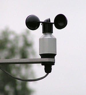
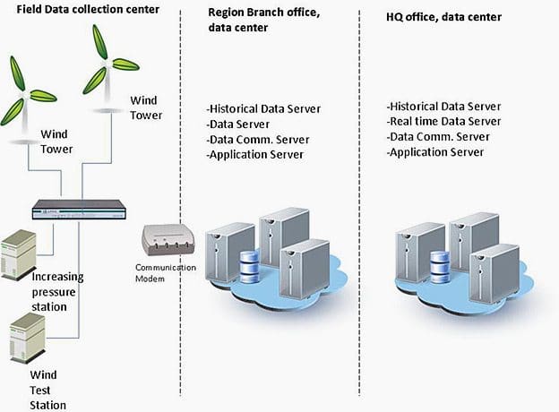
How to Monitor Wind Speed?
Sounds too long? Well, yes and no…
For a home system, this isn’t necessary. The costs involved in collecting wind data may not be justified when compared to the total cost of a small wind machine.
There is no economic formula to determine this, but it doesn’t make much sense to spend $1,200 on instrumentation if your wind machine costs only $3,000. You can get close to the actual number by making an educated guess using the empirical methods.
Options For Monitoring The Wind Speed
If you decide to monitor wind speeds, you have several options.Recording one instantaneous wind speed per day won’t do.
If you can’t record multiple wind speeds throughout a day, the quality of your data is questionable.
Click here for the full article
Monday, November 9, 2015
Maintenance of Electrical Equipment In Buildings
Purpose of Maintenance
While it is appreciated that breakdown of plant may result in costly interruption of normal building operation, it must also be borne in mind that stopping plant for maintenance can also cause a loss in production.
Equipment on continuous and arduous duty, e.g. switchboards, motor control centres (MCCs), air-handling units, chiller plant etc., require more attention than that which is lightly loaded and rarely used.
Initial Steps For Economic and Energy Efficiency
Apart from the above considerations there will be the question of whether to repair or replace faulty equipment. This requires analysis of the past and future maintenance costs and the benefits of new equipment.
There has been much operational research carried out into such things as the probability of breakdown, replacement and repair limits, and overhaul policies. This obviously requires considerable effort and expertise and may need the services of a specialist consultant.
However, some simple initial steps can be taken as far as the economic and energy efficiency is concerned for maintenance of electrical equipment in buildings.1. Standardisation of Equipment
The use as far as possible of standard items such as switchgear will help both in buying, stockholding and replacement of components on the most economic and convenient basis.Click here for the full article
Tuesday, November 3, 2015
9 Recommended Practices for Grounding
Basis for safety and power quality
Grounding and bonding are the basis upon which safety and power quality are built. The grounding system provides a low-impedance path for fault current and limits the voltage rise on the normally non-current-carrying metallic components of the electrical distribution system.During fault conditions, low impedance results in high fault current flow, causing overcurrent protective devices to operate, clearing the fault quickly and safely. The grounding system also allows transients such as lightning to be safely diverted to earth.
Bonding is the intentional joining of normally non-current-carrying metallic components to form an electrically conductive path. This helps ensure that these metallic components are at the same potential, limiting potentially dangerous voltage differences.
Careful consideration should be given to installing a grounding system that exceeds the minimum NEC requirements for improved safety and power quality.
Recommended practices for grounding
1. Equipment Grounding Conductors
The IEEE Emerald Book recommends the use of equipment-grounding conductors in all circuits, not relying on a raceway system alone for equipment grounding. Use equipment grounding conductors sized equal to the phase conductors to decrease circuit impedance and improve the clearing time of overcurrent protective devices.
Equipment grounding conductor
The minimum size the equipment grounding conductor for safety is provided in NEC 250.122, but a full-size grounding conductor is recommended for power quality considerations.
Click here for the full article
8 Energy-Efficiency Improvement Opportunities In Electric Motors
Energy Saving Opportunities
When considering energy-efficiency improvements to a facility’s motor systems, a systems approach incorporating pumps, compressors, and fans must be used in order to attain optimal savings and performance.In the following, considerations with respect to energy use and energy saving opportunities for a motor system are presented and in some cases illustrated by case studies. Pumping, fan and compressed air systems are discussed in addition to the electric motors.
Potential energy-efficiency improvements:
- Motor management plan
- Maintenance program
- Using of energy-efficient motors
- Rewinding of motors
- Proper motor sizing
- Using Adjustable speed drives (ASDs)
- Power factor correction
- Minimizing voltage unbalances
1. Motor management plan
A motor management plan is an essential part of a plant’s energy management strategy. Having a motor management plan in place can help companies realize long-term motor system energy savings and will ensure that motor failures are handled in a quick and cost effective manner.The Motor Decisions MatterSM Campaign suggests the following key elements for a sound motor management plan (CEE, 2007):
- Creation of a motor survey and tracking program.
- Development of guidelines for proactive repair/replace decisions.
- Preparation for motor failure by creating a spares inventory.
- Development of a purchasing specification.
- Development of a repair specification.
- Development and implementation of a predictive and preventive maintenance program.\
Click here to access the full article
Cable Glands For Full EMI Protection
Winning the war against
electromagnetic interference (EMI) on today’s factory floors requires attention
to detail. One of those details involves the ability of cable glands to
contribute to a reliable grounding system.
Left unprotected, cable glands
transmit electrical noise that can wreak havoc on motor-driven industrial
processes. Many types of cable glands feature shielding to keep EMI at bay, yet
the effectiveness of that shielding can
vary widely from product to product.
The ease of installation can
vary as well. Some shielding options have difficult termination methods or
grounding connections that can drive up labor cost and time.
With SKINTOP® MS-M Brush, our engineers have addressed both
the shielding and installation issues. As its name suggests, this cable gland
features a brush-type grounding connection that:
• Enhances EMI control. Unlike other
connection methods, such as the grounding clamps commonly used on drive
systems, the brush provides continuous 360° contact around the cable’s screen
braid. This continuous contact protects against EMI by lowering the resistance
of current ground path and providing a low impedance connection between the
cable shield and the housing.
• Eases Installation. Making an EMI-free
connection between cable and the SKINTOP cable gland is simple. Installers
simply insert the cable, push the screen braid into the brush and tighten the
cable gland assembly. Other grounding methods require far more effort to make
the termination. Earth sleeves, for example, can serve as an effective
grounding method, but their termination process requires precision measurements
and exacting preparation of the stripped area.
In addition to its innovative
brush-type connection, SKINTOP®
MS-M Brush offers IP 68 protection and resists temperatures up to 100ºC.
Until recently, it was available only in metric sizes, ranging from M–25X1.5 to
M–110X2.0. This month, we’ve introduced NPT sizes from ¾” to 2”.
Click here for detailed technical
information on SKINTOP® MS-M
Brush
New Industrial Ethernet Cables For Tray Applications
Industrial Ethernet offers plenty of flexibility when it
comes to designing complex automation networks.
Until recently, you couldn't say the same about data cables used in
these networks.
CAT 5e Ethernet cables have traditionally been intended for
stationary applications. And in the early days of industrial Ethernet, that
limitation didn't matter much. Modern automation systems, however, increasingly
require a new breed of Industrial Ethernet cables that can withstand more
flexible conditions.
Our new ETHERLINE® Tray cable has been designed with
flexibility in mind. With its PLTC
rating, the ETHERLINE® Tray can be used in cable trays, interconnecting the
Industrial Platform with the Commercial Infrastructure. The new ETHERLINE cable features four twisted
pairs of stranded copper, and can handle gigabit speeds.
Reliable Data
Transmission. Reliable data
transmission is a must-have if you want to control production equipment over an
Ethernet network. Unfortunately the electrical noise that pervades most
manufacturing environments makes error-free data transmission a challenge. The
new ETHERLINE cables combat electrical noise with a rugged, flex-friendly foil
and braid EMI shield.
The construction of the ETHERLINE TRAY CAT.5e consists of a
polyolefin-based insulation and a PVC jacket. The cable has a 600V rating
making it ideal for tray applications alongside power cables. When used in
flexible applications, the cable can withstand operating temperature from -25
to 80ºC. They have a characteristic
impedance of 100 Ω, ±15 Ω, at 100 MHz.
Important Approvals.
The new ETHERLINE cables have a wide range of approvals, which lets them serve
in many different settings. These approvals include:
- CMR per UL 444
- CMG per UL 444
- PLTC per UL 13
- AWM 2570 80°C 600V
- c(UL) CMG
- RoHS II
Click here , For more information on the ETHERLINE CAT.5e Tray Cable
Subscribe to:
Posts (Atom)