Wednesday, July 29, 2015

13 Basic expressions often used in electrical testing

Testing of electrical installations

This is the simple list of basic terms you can often hear when testing and measurements of electrical installation (in general) is being performed. While expirienced electrical engineers will find this list short, I hope beginners will catch the essence and continue exploring this field of electrical engineering.
Feel free to suggest me an expression (along with description) you think it should be listed, it will be my pleasure to add it to the list and to move away from number 13

Ok, so here is the list:
  1. Active accessible conductive part
  2. Passive accessible conductive part
  3. Electric shock
  4. Earthing electrode
  5. Nominal voltage
  6. Fault voltage
  7. Contact voltage
  8. Limit Contact voltage
  9. Nominal load current
  10. Nominal installation current
  11. Fault current
  12. Leakage current
  13. Short-circuit current

1. Active accessible conductive part

Active accessible conductive part is the conductive part of an electrical installation or appliance such as the housing, part of a housing etc. which can be touched by a human body. Such an accessible part is free of mains voltage except under fault conditions.
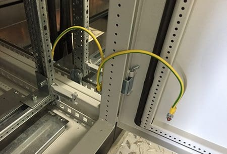
Switchboard contruction grounded
Switchboard contruction grounded (photo credit: ecsanyi)

2. Passive accessible conductive part

Passive accessible conductive part is an accessible conductive part, which is not a part of an electrical installation or appliance, like:
  • Heating system pipes,
  • Water pipes,
  • Metal parts of air condition system,
  • Metal parts of building framework
  • etc.

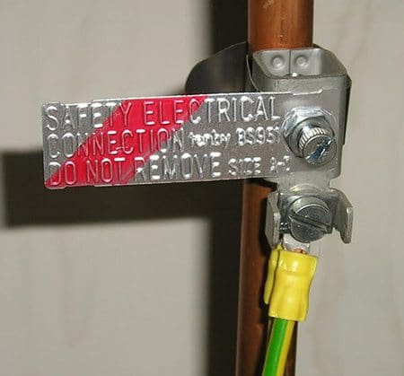
Equipotential bonding of metal pipes
Equipotential bonding of metal pipes (photo credit: diy.stackexchange.com)
Click here to access the full article

Friday, July 10, 2015

How to measure insulation resistance of a motor

Winding insulation resistance

If the motor is not put into operation immediately upon arrival, it is important to protect it against external factors like moisture, high temperature and impurities in order to avoid damage to the insulation. Before the motor is put into operation after a long period of storage, you have to measure the winding insulation resistance.

If the motor is kept in a place with high humidity, a periodical inspection is necessary.
It is practically impossible to determine rules for the actual minimum insulation resistance value of a motor because resistance varies according to method of construction, condition of insulation material used, rated voltage, size and type. In fact, it takes many years of experience to determine whether a motor is ready for operation or not.

A general rule-of-thumb is 10 Megohm or more.

 Insulation resistance value Insulation level
 2 Megohm or less Bad
 2-5 Megohm Critical
 5-10 Megohm Abnormal
 10-50 Megohm Good
 50-100 Megohm Very good
 100 Megohm or more Excellent

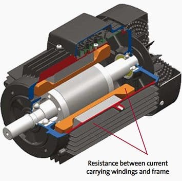
The measurement of insulation resistance is carried out by means of a megohmmeter – high resistance range ohmmeter. This is how the test works: DC voltage of 500 or 1000 V is applied between the windings and the ground of the motor. Ground insulation test of a motor

Ground insulation test of a motor


During the measurement and immediately afterwards, some of the terminals carry dangerous voltages and MUST NOT BE TOUCHED.
Now, three points are worth mentioning in this connection: Insulation resistance, Measurement and Checking.

Click here for the full article 

Online Tool Sizes VFD Cables

A new online engineering calaculator that helps users select varaible frequency drive (VFD) cables that meet their application requirements.

This new mobile-friendly sizing tool prompts  the user to enter the application's horsepower and voltage or full load current and voltage. It then calculates wire gauge. Based on this information, the sizing tool then recommends appropriate VFD cables and provides technical specifications. A request for pricing can also be submitted directly through the applications.

 Lapp's line of VFD is used in a wide range of automation, packaging and alternative energy applications.

To use our online sizing tool, visit http://www.lapp-applications.com/vfdselect


Thursday, June 18, 2015

Electrical Thumb Rules You MUST Follow (Part 1)

Cable Capacity

  • For Cu Wire Current Capacity (Up to 30 Sq.mm) = 6X Size of Wire in Sq.mm
    Ex. For 2.5 Sq.mm = 6×2.5 = 15 Amp, For 1 Sq.mm = 6×1 = 6 Amp, For 1.5 Sq.mm = 6×1.5 = 9 Amp
  • For Cable Current Capacity = 4X Size of Cable in Sq.mm, Ex. For 2.5 Sq.mm = 4×2.5 = 9 Amp.
  • Nomenclature for cable Rating = Uo/U
  • where Uo = Phase-Ground Voltage, U = Phase-Phase Voltage, Um = Highest Permissible Voltage

Current Capacity of Equipment

  • 1 Phase Motor draws Current = 7Amp per HP.
  • 3 Phase Motor draws Current = 1.25Amp per HP.
  • Full Load Current of 3 Phase Motor = HPx1.5
  • Full Load Current of 1 Phase Motor = HPx6
  • No Load Current of 3 Phase Motor = 30% of FLC
  • KW Rating of Motor = HPx0.75
  • Full Load Current of equipment = 1.39xKVA (for 3 Phase 415Volt)
  • Full Load Current of equipment = 1.74xKw (for 3 Phase 415Volt)

Earthing Resistance

  • Earthing Resistance for Single Pit = 5Ω, Earthing Grid = 0.5Ω
  • As per NEC 1985 Earthing Resistance should be < 5Ω.
  • Voltage between Neutral and Earth <= 2 Volt
  • Resistance between Neutral and Earth <= 1Ω
  • Creepage Distance18 to 22mm/KV (Moderate Polluted Air) or
  • Creepage Distance = 25 to 33mm/KV (Highly Polluted Air)

Minimum Bending Radius

  • Minimum Bending Radius for LT Power Cable = 12 x Dia of Cable.
  • Minimum Bending Radius for HT Power Cable = 20 x Dia of Cable.
  • Minimum Bending Radius for Control Cable = 10 x Dia of Cable.
  •  

Insulation Resistance

  • Insulation Resistance Value for Rotating Machine = (KV+1) MΩ.
  • Insulation Resistance Value for Motor (IS 732) = ((20xVoltage (L-L)) / (1000+ (2xKW)).
  • Insulation Resistance Value for Equipment (<1KV) = Minimum 1 MΩ.
  • Insulation Resistance Value for Equipment (>1KV) = KV 1 MΩ per 1KV.
  • Insulation Resistance Value for Panel = 2 x KV rating of the panel.
  • Min Insulation Resistance Value (Domestic) = 50 MΩ / No of Points. (All Electrical Points with Electrical fitting & Plugs). Should be less than 0.5 MΩ
  • Min Insulation Resistance Value (Commercial) = 100 MΩ / No of Points. (All Electrical Points without fitting & Plugs).Should be less than 0.5 MΩ.
  • Test Voltage (A.C) for Meggering = (2X Name Plate Voltage) +1000
  • Test Voltage (D.C) for Meggering = (2X Name Plate Voltage).
  • Submersible Pump Take 0.4 KWH of extra Energy at 1 meter drop of Water.
 
Click here for full article

Wednesday, June 17, 2015

Basics of DC Motors For Electrical Engineers – Beginners


General about DC motors

Separate field excitation DC motors are still sometimes used for driving machines at variable speed. These motors are very easy to miniaturize, and essential for very low powers and low voltages.

They are also particularly suitable, up to high power levels (several megawatts), for speed variation with simple, uncomplicated electronic technologies for high performance levels (variation range commonly used from 1 to 100).

Their characteristics also enable accurate torque regulation, when operating as a motor or as a generator. Their nominal rotation speed, which is independent of the line supply frequency, is easy to adapt by design to suit all applications.
 
They are however less rugged than asynchronous motors and much more expensive, in terms of both hardware and maintenance costs, as they require regular servicing of the commutator and the brushes.

Construction of DC motor //

DC motor construction parts

A DC motor is composed of the following main parts:

Field coil or stator

This is a non-moving part of the magnetic circuit on which a winding is wound in order to produce a magnetic field. The electro-magnet that is created has a cylindrical cavity between its poles.

Armature or rotor

This is a cylinder of magnetic laminations that are insulated from one another and perpendicular to the axis of the cylinder. The armature is a moving part that rotates round its axis, and is separated from the field coil by an air gap. Conductors are evenly distributed around its outer surface.

Commutator and brushes

The commutator is integral with the armature. The brushes are fixed. They rub against the commutator and thus supply power to the armature conductors.


Click here for the full article


Tuesday, June 2, 2015

Few Aspects of Copper versus Aluminium

Conductor connections and terminations

The constructions of aluminum wire and terminals have both been revised from past years. At one time the conductor was nearly pure aluminum, now they are all much stronger 8000 series alloys, with physical characteristics similar to copper.
The wire terminations also have much more severe UL test requirements, resulting in reliable long-term connections when installed in accordance with instructions. There is a common misconception that only compression (crimp) lugs should be used with aluminum cables, but this is not true.
In the past with the use of the softer aluminum conductors, only compression connectors were suitable. However with the aluminum conductors used today and modern design and plating of mechanical pressure connectors, compression connectors are no longer required.
The terminals on molded case circuit breakers are typically plated aluminum alloy with mechanical setscrews, listed for use with either aluminum or copper conductors.


These lugs rated ALCU alleviate the need for more expensive compression connectors and the more laborious installations for these connectors.
The substitution of aluminum wire for copper always involves size and can also impact quantity. The size increase is usually one or two wire sizes.
It is more common to have compact stranding of aluminum wire than copper, which can reduce the conduit upsizing required. Even though physically larger the aluminum wire is lighter and easier to handle than the equivalent copper conductor. In
most cases the same lug can accommodate either aluminum or copper and has adequate wire range.
Any lug marked ALCU is suitable for use with either conductor. Another factor with the use of aluminum wiring for the supply or load from a piece of the electrical equipment is the size of the conduits. The use of aluminum conductors will result in either larger conductor size or more quantity of conductors. Either way, more or larger conduits will be utilized.
A design trend is always toward equipment with smaller footprints. Cost of the space in the structures housing the equipment is constantly increasing.
However in many cases there might not be physical space in the equipment for the termination of the conduits using aluminum conductors while there is adequate space for the quantity and size of the conduits for the copper conductors.

Click here to read the full article

Wednesday, May 20, 2015

5 Most Common Motor Load Types

5 Most Common Motor Load Types

Load profile (speed range, torque and power)

Certain load types are characteristic in the industrial world. Knowing the load profile (speed range, torque and power) is essential when selecting a suitable motor and frequency converter for the application.
Some common load types are shown. There may also be combinations of these types.
  1. Constant Torque
  2. Quadratic torque
  3. Constant power
  4. Constant power/torque
  5. Starting/breakaway torque demand

1. Constant torque

A constant torque load type is typical when fixed volumes are being handled. For example screw compressors, feeders and conveyors are typical constant torque applications.
Torque is constant and the power is linearly proportional to the speed.
Typical torque and power curves in a constant torque application
Figure 1 – Typical torque and power curves in a constant torque application


2. Quadratic torque

Quadratic torque is the most common load type. Typical applications are centrifugal pumps and fans. The torque is quadratically, and the power is cubically proportional to the speed.
Typical torque and power curves in a quadratic torque application
Figure 2 – Typical torque and power curves in a quadratic torque application

3. Constant power

A constant power load is normal when material is being rolled and the diameter changes during rolling. The power is constant and the torque is inversely proportional to the speed.
Typical torque and power curves in a constant power application
Figure 3 – Typical torque and power curves in a constant power application

4. Constant power/torque

This load type is common in the paper industry. It is a combination of constant power and constant torque load types. This load type is often a consequence of dimensioning the system according to the need for certain power at high speed.
Typical torque and power curves in a constant power/torque application
Figure 4 – Typical torque and power curves in a constant power/torque application

5. Starting/breakaway torque demand

In some applications high torque at low frequencies is needed. This has to be considered in dimensioning. Typical applications for this load type are for example extruders and screw pumps.
Typical torque curve in an application where starting torque is needed
Figure 5 – Typical torque curve in an application where starting torque is needed

Click here for the full article