Monday, April 18, 2016

Two Basic Methods Used For Braking a Motor (DC Injection and Dynamic)

Braking a Motor

Two common basic methods used for braking a motor are DC injection braking and dynamic braking. We will look at both in detail, starting with electric braking.
  1. DC Injection Braking
  2. Dynamic Braking

1. DC Injection Braking

DC injection braking is a method of braking in which direct current (DC) is applied to the stationary windings of an AC motor after the AC voltage is removed. This is an efficient and effective method of braking most AC motors.
DC injection braking provides a quick and smooth braking action on all types of loads, including high- speed and high-inertia loads.
Recall that opposite magnetic poles attract and like magnetic poles repel. This principle, when applied to both AC and DC motors, is the reason why the motor shaft rotates.
DC injection braking of a motor
Figure 1 – DC injection braking of a motor

In an AC induction motor, when the AC voltage is removed, the motor will coast to a standstill over a period of time, since there is no induced field to keep it rotating. Since the coasting time may be unacceptable, particularly in an emergency situation, electric braking can be used to provide a more immediate stop.
By applying a DC voltage to the stationary windings once the AC is removed, a magnetic field is created in the stator that will not change polarity.
In turn, this constant magnetic field in the stator creates a magnetic field in the rotor. Since the magnetic field of the stator is not changing in polarity, it will attempt to stop the rotor when the magnetic fields are aligned (N to S and S to N).

DC injection motor braking demonstration (VIDEO)

The only thing that can keep the rotor from stopping with the first alignment is the rotational inertia of the load connected to the motor shaft. However, since the braking action of the stator is present at all times, the motor is braked quickly and smoothly to a standstill.

Since there are no parts that come in physical contact during braking, maintenance is kept to a minimum.

Click here to access the full article

Tuesday, April 12, 2016

What Would Be The Best Conductor Material for Electrical Cables


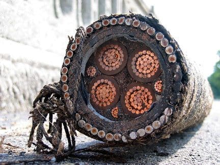
HV copper cable (photo credit: businessinsider.com)

Al or Cu conductor…


What Would Be The Best Conductor Material for Electrical CablesThe conductivity of copper is 65% higher than that of aluminium which means that the conductor size of similarly rated cables is proportionately smaller. Correspondingly less expense is then incurred in providing for insulation, shielding and armouring the cables themselves. Transport of the less-bulky cables is easier and so is installation. In limited spaces in cable ducts, the smaller volume and better ductility of copper cables can have an even larger benefit.
Copper cables are easily jointed because copper does not form on its surface a tough, non-conducting oxide. The oxide film that does form is thin, strongly adherent and electrically conductive, causing few problems.


Cleaning and protection of copper is easy and if joints are made as recommended they will not deteriorate to any great extent with age, which saves on maintenance costs.

HV copper cableFor the same nominal current rating, the cable with the aluminium conductor is significantly larger in diameter, carries a proportionally greater volume of insulation and is not so easily installed because of being less flexible. Aluminium is notoriously difficult to joint reliably. Table 1 compares aluminium and copper conductors for equivalent current rating.


Table 1 – Comparison between Copper and Aluminium Conductors in XLPE Insulated Steel- Wire Armoured Cables.
 
Characteristic Copper 300 m2 Aluminium 500 m
Overall diameter (mm) 66.5 83.9
Minimum bending radius (mm) 550 700
Max DC resistance/km at 20o C (ohm) 0.0601 0.0617
Approx. voltage drop/A/m (mV) 0.190 0.188
Continuous current rating, drawn in to duct (amp) 496 501

(Cable: to BS 5467 (& IEC 502) 4-core, stranded conductors, XLPE insulation, PVC bedding, steel wire armour, PVC oversheath, rated at 0.6/1.0 kV)


These notes have largely been derived from reference to BS 7450 which is identical to IEC 1059. Both of these give full details of the variables to be considered and the ways in which optimum cable size determinations can be made.

Click here to access the full article

Thursday, March 31, 2016

18 Key Terms Defined In NEC System Grounding Requirements

System Grounding Arrangement

The topic of system grounding is extremely important, as it affects the susceptibility of the system to voltage transients, determines the types of loads the system can accommodate, and helps to determine the system protection requirements.
The system grounding arrangement is determined by the grounding of the power source. For commercial and industrial systems, the types of power sources generally fall into four broad categories:
  1. Utility Service – The system grounding is usually determined by the secondary winding configuration of the upstream utility substation transformer.
  2. Generator – The system grounding is determined by the stator winding configuration.
  3. Transformer – The system grounding on the system fed by the transformer is determined by the transformer secondary winding configuration.
  4. Static Power Converter – For devices such as rectifiers and inverters, the system grounding is determined by the grounding of the output stage of the converter.
Categories 1 to 4 fall under the NEC definition for a “separately-derived system”. The recognition of a separately-derived system is important when applying NEC requirements to system grounding. The National Electrical Code does place constraints on system grounding.
As a starting point, 18 key terms from the NEC need to be defined:

1. Ground

A conducting connection, whether intentional or accidental, between an electrical circuit or equipment and the earth or to some body that serves in place of the earth.
Ground definition
Ground definition (photo credit: ibiblio.org)

2. Grounded

Connected to earth or to some body that serves in place of the earth.

3. Effectively Grounded

Intentionally connected to earth through a ground connection or connections of sufficiently low impedance and having sufficient current-carrying capacity to prevent the buildup of voltages that may result in undue hazards to connected equipment or to persons.

4. Grounded Conductor

A system or circuit conductor that is intentionally grounded.
Grounding simple scheme
Grounding simple scheme (photo credit: diy.stackexchange.com)

5. Solidly Grounded

Connected to ground without inserting any resistor or impedance device.

6. Grounding Conductor

A conductor used to connect equipment or the grounded circuit of a wiring system to a grounding electrode or electrodes.

Click here to access the full article
4 Practical Approaches To Minimize Voltage Drop Problems

What NEC states for max. voltage drop?

The NEC states in an Informational Note that a maximum voltage drop of 3% for branch circuit conductors, and 5% for feeder and branch circuit conductors together, will provide reasonable efficiency of operation for general use circuits.
4 Practical Approaches To Minimize Voltage Drop ProblemsFor sensitive electronic loads, circuits should be designed for a maximum of 1.5% voltage drop for branch circuits at full load, and 2.5% voltage drop for feeder and branch circuits combined at full load.


1. Increase the Number or Size of Conductors

Parallel or oversized conductors have lower resistance per unit length than the Code-required minimum-sized conductors, reducing voltage drop and increasing energy efficiency with lower losses than using the Code-required minimum-sized conductor.
In data centers and other sensitive installations, it is not uncommon to find conductor gauges for phase, neutral, and ground exceeding Code minimums, and a separate branch circuit installed for each large or sensitive load.
To limit neutral-to-ground voltage drop, install a separate, full-sized neutral conductor for each phase conductor in single-phase branch circuit applications.
For three-phase feeder circuits, do not downsize the grounded conductor or neutral. For three-phase circuits where significant non-linear loads are anticipated, it is recommended to install grounded or neutral conductors with at least double the ampacity of each phase conductor.

2. Decrease Load Current

Limiting the amount of equipment that can be connected to a single circuit will limit the load current on the circuit. Limit the number of receptacles on each branch circuit to three to six.
Install individual branch circuits to sensitive electronic loads or loads with a high inrush current.
For residential applications, install outdoor receptacles not to exceed 50 linear feet between receptacles, with a minimum of one outdoor receptacle on each side of the house, and with individual branch circuits with a minimum of 12 AWG to each receptacle.


Click here to access the full article

Wednesday, March 16, 2016

Recommended Practice For Cableways Selection and Installation


Cableway

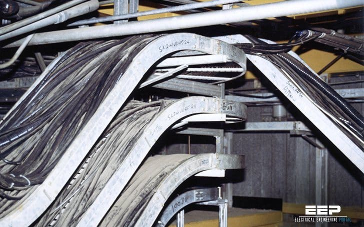
The term cableways refers to conductors and/or cables together with the means of support and protection, etc. for example: cable trays, ladders, ducts, trenches, and so on… are all cableways. This technical article covers the following topics //

Selection of materials and shapes

Selection of materials and their shape depends on the following criteria //
    Recommended Practice For Cableways Selection and Installation
  • Severity of the electromagnetic (EM) environment along cableways (proximity of sources of conducted or radiated EM disturbances)
  • Authorised level of conducted and radiated emissions
  • Type of cables (shielded?, twisted?, optical fibre?)
  • EMI withstand capacity of the equipment connected to the wiring system
  • Other environmental constraints (chemical, mechanical, climatic, re, etc.)
  • Future extensions planned for the wiring system
Non-metal cableways are suitable in the following cases //
  • A continuous, low-level EM environment
  • A wiring system with a low emission level
  • Situations where metal cableways should be avoided (chemical environment)
  • Systems using optical fibres
For metal cableways, it is the shape (at, U-shape, tube, etc.) rather than the cross-sectional area that determines the characteristic impedance.
Closed shapes are better than open shapes because they reduce common-mode coupling. Cableways often have slots for cable straps. The smaller the better. The types of slots causing the fewest problems are those cut parallel and at some distance from the cables.
Slots cut perpendicular to the cables are not recommended (see Figure 1).
CEM performance of various types of metal cableways

In certain cases, a poor cableway in EMI terms may be suitable if the EM environment is low, if shielded cables or optical bres are employed, or separate cableways are used for the different types of cables (power, data processing, etc.).
It is a good idea to reserve space inside the cableway for a given quantity of additional cables.
The height of the cables must be lower than the partitions of the cableway as shown below. Covers also improve the EMC performance of cableways. In U-shaped cableways, the magnetic field decreases in the two corners.The picture below explains why deep cableways are preferable (see
Installation of different types of cables

Different types of cables (power and low-level cables) should not be installed in the same bundle or in the same cableway. Cableways should never be filled to more than half capacity!!

Click here to read the full article

Tuesday, March 15, 2016

General considerations when choosing power cable


Copper or Aluminium?

Thousands of cable types are used throughout the world. They are found in applications ranging from fibre-optic links for data and telecommunication purposes through to EHV underground power transmission at 275 kV or higher.

Certain design principles are common to power cables, whether they are used in the industrial sector or by the electricity supply industry. For many cable types the conductors may be of copper or aluminium.
 
The initial decision made by a purchaser will be based on price, weight, cable diameter, availability, the expertise of the jointers available, cable flexibility and the risk of theft.

What to choose?

Once a decision has been made, however, that type of conductor will generally then be retained by that user, without being influenced by the regular changes in relative price which arise from the volatile metals market.
For most power cables the form of conductor will be solid aluminium, stranded aluminium, solid copper (for small wiring sizes) or stranded copper, although the choice may be limited in certain cable standards.
Solid conductors provide for easier fitting of connectors and setting of the cores at joints and terminations. Cables with stranded conductors are easier to install because of their greater flexibility, and for some industrial applications a highly flexible conductor is necessary.

Where cable route lengths are relatively short, a multi-core cable is generally cheaper and more convenient to install than single-core cable.

Single-core cables are sometimes used in circuits where high load currents require the use of large conductor sizes, between 500 mm2 and 1200 mm2.
 
In these circumstances, the parallel connection of two or more multi-core cables would be necessary in order to achieve the required rating and this presents installation difficulties, especially at termination boxes.

Click here to access the full article

Tuesday, March 8, 2016

Reliable VFD cables Boost Productivity, Minimize Downtime


Variable frequency drives (VFDs) are a mainstay of the industrial world due to their remarkable ability to improve the efficiency of motor-driven equipment. As part of a complete VFD package, high quality cable is one of the most important components in terms of achieving maximum productivity and minimizing downtime. 

When designing a robust VFD cable, the materials used in its production are critical to ensuring that the cable’s electrical properties will guarantee peak performance. 

For system engineers and others involved in specifying VFDs, cable quality should be one of the most decisive factors.

What's Inside:
  • VFD theory simplified
  • The problem with cable
  • The importance of selecting the right insulation material
  • How to maintain cable integrity with proper shielding
  • Regulatory compliance issues


Click here to download your copy