Thursday, September 17, 2015

The Best Applications for Variable Frequency Drives (VFDs)

Advances

The most commonly used motor in building HVAC applications is the three-phase, induction motor, although some smaller applications may use a single-phase induction motor.
The Best Applications For Variable Frequency Drives (VFDs)VFDs can be applied to both.
While VFD controllers can be used with a range of applications, the ones that will produce the most significant benefits are those that require variable speed operation.
For example, the flow rate produced by pumps serving building HVAC systems can be matched to the building load by using a VFD to vary the flow rate.
Similarly, in systems that require a constant pressure be maintained regardless of the flow rate, such as in domestic hot and cold water systems, a VFD controlled by a pressure setpoint can maintain the pressure over most demand levels.

The majority of commercial and institutional HVAC systems use variable volume fan systems to distribute conditioned air. Most are controlled by a system of variable inlet vanes in the fan system and variable air volume boxes.
 
As the load on the system decreases, the variable air volume boxes close down, increasing the static pressure in the system. The fan’s controller senses this increase and closes down its inlet vanes. While using this type of control system will reduce system fan energy requirements, it is not as efficient or as accurate as a VFD-based system.

Another candidate for VFD use is a variable refrigerant flow systems. Variable refrigerant flow systems connect one or more compressors to a common refrigerant supply system that feeds multiple evaporators. By piping refrigerant instead of using air ducts, the distribution energy requirements are greatly reduced.
Because the load on the compressor is constantly changing based on the demand from the evaporators, a VFD can be used to control the operating speed of the compressor to match the load, reducing energy requirements under part-load conditions.

Additional VFD Applications

While the primary benefit of both of these VFD applications is energy savings, VFDs are well suited for use in other applications where energy conservation is of secondary importance. For example, VFDs can provide precise speed or torque control in some commercial applications.
Some specialized applications use dual fans or pumps. VFDs, with their precise speed control, can ensure that the two units are operated at the desired speed and do not end up fighting each other or having one unit carry more than its design load level.
Advances in technology have increased the number of loads that can be driven by the units. Today, units are available with voltage and current ratings that can match the majority of three-phase induction motors found in buildings. With 500 horsepower units or higher available, facility executives have installed them on large capacity centrifugal chillers where very large energy savings can be achieved.
One of the most significant changes that has taken place recently is that with the widespread acceptance of the units and the recognition of the energy and maintenance benefits, manufacturers are including VFD controls as part of their system in a number of applications. For example, manufacturers of centrifugal chillers offer VFD controls as an option on a number of their units.
Similarly, manufacturers of domestic water booster pump systems also offer the controls as part of their system, providing users with better control strategies while reducing energy and maintenance costs.

Click here to access the full article


Wednesday, September 16, 2015

Cable Spacing as a Means of Noise Mitigation

Separation distances

Cable spacing as a means of noise mitigation
In situations where there are a large number of cables varying in voltage and current levels, the IEEE 518-1982 standard has developed a useful set of tables indicating separation distances for the various classes of cables.
There are four classification levels of susceptibility for cables.
Susceptibility, in this context, is understood to be an indication of how well the signal circuit can differentiate between the undesirable noise and required signal. It follows that a data communication physical standard such as RS-232E would have a high susceptibility, and a 1000-V, 200-A AC cable has a low susceptibility.

IEEE 518 – 1982 standard

The four susceptibility levels defined by the IEEE 518 – 1982 standard are briefly:

Level 1 (High) – This is defined as analog signals less than 50 V and digital signals less than 15 V. This would include digital logic buses and telephone circuits. Data communication cables fall into this category.
Level 2 (Medium) – This category includes analog signals greater than 50 V and switching circuits.
Level 3 (Low) – This includes switching signals greater than 50 V and analog signals greater than 50 V. Currents less than 20 A are also included in this category.
Level 4 (Power) – This includes voltages in the range 0–1000 V and currents in the range 20–800 A. This applies to both AC and DC circuits.
The IEEE 518 also provides for three different situations when calculating the separation distance required between the various levels of susceptibilities. In considering the specific case where one cable is a high-susceptibility cable and the other cable has a varying susceptibility, the required separation distance would vary as follows:

Both cables contained in a separate tray:
  • Level 1 to level 2-30 mm
  • Level 1 to level 3-160 mm
  • Level 1 to level 4-670 mm
One cable contained in a tray and the other in conduit:
  • Level 1 to level 2-30 mm
  • Level 1 to level 3-110 mm
  • Level 1 to level 4-460 mm
Both cables contained in separate conduit:
  • Level 1 to level 2-30 mm
  • Level 1 to level 3-80 mm
  • Level 1 to level 4-310 mm.
The figures are approximate as the original standard is quoted in inches.

Trays and conduits


A few words need to be said about the construction of the trays and conduits. It is expected that the trays are manufactured from metal and be firmly earthed with complete continuity throughout the length of the tray. The trays should also be fully covered preventing the possibility of any area being without shielding.

Briefly galvanic noise can easily be avoided by refraining from the use of a shared signal reference conductor, in other words, keeping the two signal channels galvanically separate so that no interference takes place.
 
Electromagnetic induction can be minimized in several ways. One way is to put the source of electromagnetic flux within a metallic enclosure, a magnetic screen. Such a screen restricts the flow of magnetic flux from going beyond its periphery so that it cannot interfere with external conductors. A similar screen around the receptor of EMI can mitigate noise by not allowing flux lines inside its enclosure but to take a path along the plane of its surface.

Physical separation between the noise source and the receptor will also reduce magnetic coupling and therefore the interference.

 
Click here to access the full article

An example how to calculate voltage drop and size of electrical cable

Input information

Electrical details:

Electrical load of 80KW, distance between source and load is 200 meters, system voltage 415V three phase, power factor is 0.8, permissible voltage drop is  5%, demand factor is 1.

Cable laying detail:

An example how to calculate voltage drop and size of electrical cableCable is directed buried in ground in trench at the depth of 1 meter. Ground temperature is approximate 35 Deg. Number of cable per trench is 1. Number of run of cable is 1 run.

Soil details:

Thermal resistivity of soil is not known. Nature of soil is damp soil.


Ok, let’s dive into calculations…

  • Consumed Load = Total Load · Demand Factor:
    Consumed Load in KW = 80 · 1 = 80 KW
  • Consumed Load in KVA = KW/P.F.:
    Consumed Load in KVA = 80/0.8 = 100 KVA
  • Full Load Current = (KVA · 1000) / (1.732 · Voltage):
    Full Load Current = (100 · 1000) / (1.732 · 415) = 139 Amp.

Click here to access the full article

Tuesday, September 1, 2015

How to wire a HA 3/4 Rectangular Connector

HA Series connectors are used whenever space is limited. They provide the smallest possible footprint in a 10A power connector. Wiring a HA 3 series connector takes less than 10 min. Watch this video to learn how
 

Visit the Lapp Group website to access our comprehensive line of industrial connectors. 


Monday, August 31, 2015

3 Conditions That Can Damage Your PLC

PLC in adverse conditions

In certain applications, the operating environment may have extreme conditions that require special attention or otherwise can seriously damage PLCs. These adverse conditions include excessive noise and heat and nuisance line fluctuations. This article describes these conditions and provide measures to minimize their effects.
  1. Excessive noise
  2. Excessive heat
  3. Nuisance line fluctuations

1. Excessive Noise

Electrical noise seldom damages PLC components, unless extremely high energy or high voltage levels are present. However, temporary malfunctions due to noise can result in hazardous machine operation in certain applications. Noise may be present only at certain times, or it may appear at widespread intervals. In some cases, it may exist continuously.
The first case is the most difficult to isolate and correct.
Noise usually enters a system through input, output, and power supply lines. Noise may also be coupled into these lines electrostatically through the capacitance between them and the noise signal carrier lines.
The presence of high-voltage or long, closely spaced conductors generally produces this effect. The coupling of magnetic fields can also occur when control lines are located close to lines carrying large currents.
Devices that are potential noise generators include relays, solenoids, motors, and motor starters, especially when operated by hard contacts, such as push buttons and selector switches.
Suppression of a three-phase motor lead
Figure 1 – Suppression of a three-phase motor lead

Analog I/O and transmitters are very susceptible to noise from electromechanical sources, causing jumps in counts during the reading of analog data. Therefore, motor starters, transformers, and other electromechanical devices should be kept away from analog signals, interfaces, and transmitters.
Although the design of solid-state controls provides a reasonable amount of noise immunity, the designer must still take special precautions to minimize noise, especially when the anticipated noise signal has characteristics similar to the desired control input signals.
IMPORTANT // To increase the operating noise margin, the controller must be installed away from noise-generating devices, such as large AC motors and high-frequency welding machines. Also, all inductive loads must be suppressed. Three-phase motor leads should be grouped together and routed separately from low-level signal leads.
Sometimes, if the noise level situation is critical, all three-phase motor leads must be suppressed (see Figure 1 above). Figure 2 illustrates line-filtering configurations used for removing input power noise to a controller or transmitter.
Power noise reduction using one of three line-filtering configurations
Figure 2 – Power noise reduction using one of three line-filtering configurations

Note 1 Keep line filters 12 inches or less from the controller. Minimize the line distance where noise can be introduced into the controller.
Note 2 To prevent ground loops, do not tie the common mode line metal case filters with other metal that is at ground potential. Doing so will reduce the filters’ effectiveness.

For the full article, click here

Wednesday, July 29, 2015

13 Basic expressions often used in electrical testing

Testing of electrical installations

This is the simple list of basic terms you can often hear when testing and measurements of electrical installation (in general) is being performed. While expirienced electrical engineers will find this list short, I hope beginners will catch the essence and continue exploring this field of electrical engineering.
Feel free to suggest me an expression (along with description) you think it should be listed, it will be my pleasure to add it to the list and to move away from number 13

Ok, so here is the list:
  1. Active accessible conductive part
  2. Passive accessible conductive part
  3. Electric shock
  4. Earthing electrode
  5. Nominal voltage
  6. Fault voltage
  7. Contact voltage
  8. Limit Contact voltage
  9. Nominal load current
  10. Nominal installation current
  11. Fault current
  12. Leakage current
  13. Short-circuit current

1. Active accessible conductive part

Active accessible conductive part is the conductive part of an electrical installation or appliance such as the housing, part of a housing etc. which can be touched by a human body. Such an accessible part is free of mains voltage except under fault conditions.

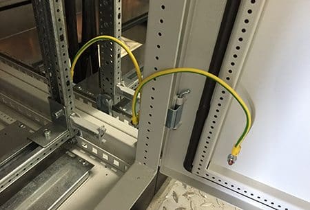
Switchboard contruction grounded
Switchboard contruction grounded (photo credit: ecsanyi)

2. Passive accessible conductive part

Passive accessible conductive part is an accessible conductive part, which is not a part of an electrical installation or appliance, like:
  • Heating system pipes,
  • Water pipes,
  • Metal parts of air condition system,
  • Metal parts of building framework
  • etc.

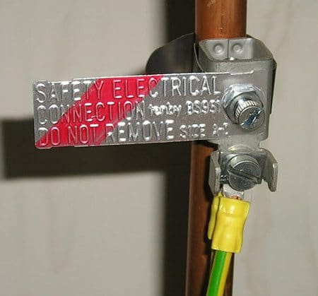
Equipotential bonding of metal pipes
Equipotential bonding of metal pipes (photo credit: diy.stackexchange.com)
Click here to access the full article

Friday, July 10, 2015

How to measure insulation resistance of a motor

Winding insulation resistance

If the motor is not put into operation immediately upon arrival, it is important to protect it against external factors like moisture, high temperature and impurities in order to avoid damage to the insulation. Before the motor is put into operation after a long period of storage, you have to measure the winding insulation resistance.

If the motor is kept in a place with high humidity, a periodical inspection is necessary.
It is practically impossible to determine rules for the actual minimum insulation resistance value of a motor because resistance varies according to method of construction, condition of insulation material used, rated voltage, size and type. In fact, it takes many years of experience to determine whether a motor is ready for operation or not.

A general rule-of-thumb is 10 Megohm or more.

 Insulation resistance value Insulation level
 2 Megohm or less Bad
 2-5 Megohm Critical
 5-10 Megohm Abnormal
 10-50 Megohm Good
 50-100 Megohm Very good
 100 Megohm or more Excellent

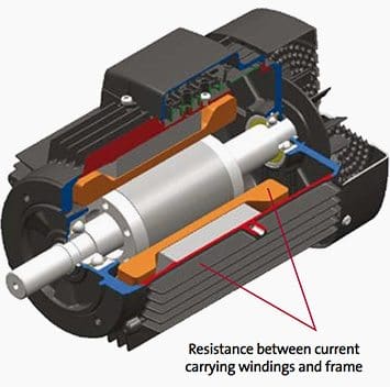
The measurement of insulation resistance is carried out by means of a megohmmeter – high resistance range ohmmeter. This is how the test works: DC voltage of 500 or 1000 V is applied between the windings and the ground of the motor. Ground insulation test of a motor

Ground insulation test of a motor


During the measurement and immediately afterwards, some of the terminals carry dangerous voltages and MUST NOT BE TOUCHED.
Now, three points are worth mentioning in this connection: Insulation resistance, Measurement and Checking.

Click here for the full article