Electrical equipment uses a wide variety of wire and cable types and
it is up to us to be able to correctly identify and use the wires which
have been specified. The wrong wire types will cause operational problems and could render the unit unsafe. Such factors include:
The insulation material;
The size of the conductor;
What it’s made of;
Whether it’s solid or stranded and flexible.
These are all considerations which the designer has to take into account to suit the final application of the equipment.
A conductor is a material which will allow an electric current to
flow easily. In the case of a wire connection, it needs to be a very
good conductor. Good conductors include most metals. The most common
conductor used in wire is copper, although you may come across others such as aluminium. An insulator on the other hand is a material which does not allow an electric current to flow. Rubber and most plastics are insulators. Preparing wire
Insulation materials
Wires and cables (conductors) are insulated and protected by a variety of materials (insulators)
each one having its own particular properties. The type of material
used will be determined by the designer who will take into account the
environment in which a control panel or installation is expected to
operate as well as the application of individual wires within the panel. As part of the insulating function, a material may have to withstand without failing:
Extremes of current or temperature;
A corrosive or similarly harsh environment;
Higher voltages than the rest of the circuit.
Because of these different properties and applications, it is
essential that you check the wiring specification for the correct type
to use.
A common approach to test cable and determine insulation integrity is to use a Hi-pot test.
In a hi-pot test, a DC voltage is applied for 5 to 15 min. IEEE-400
specifies that the hi-pot voltage for a 15-kV class cable is 56 kV for an
acceptance test and 46 kV for a maintenance test
(ANSI/IEEE Std. 400-1980). Other industry standard tests are given in
(AEIC CS5-94, 1994; AEIC CS6-96, 1996; ICEA S-66-524, 1988). High-pot
testing is a brute-force test; imminent failures are detected, but the
amount of deterioration due to aging is not quantified (go/no-go test).
The DC test is controversial
– some evidence has shown that hi-pot testing may damage XLPE cable
(Mercier and Ticker, 1998). EPRI work has shown that dc testing
accelerates treeing (EPRI TR-101245, 1993; EPRI TR-101245-V2, 1995).
For Hi-pot testing of 15-kV, 100% insulation (175-mil, 4.445-mm) XLPE cable, EPRI recommended:
Do not do testing at 40 kV (228 V/mil) on cables that are aged
(especially those that failed once in service and then are spliced).
Above 300 V/mil, deterioration was predominant.
New cable can be tested at the factory at 70 kV. No effect on cable life was observed for testing of new cable.
New cable can be tested at 55 kV in the field prior to energization if aged cable has not been spliced in.
Testing at lower dc voltages (such as 200 V/mil) will not pick out bad sections of cable.
Another option for testing cable integrity: ac testing does not
degrade solid dielectric insulation (or at least degrades it more
slowly). The use of very low frequency AC testing (at about 0.1 Hz) may
cause less damage to aged cable than DC testing (Eager et al., 1997)
(but utilities have reported that it is not totally benign, and ac
testing has not gained widespread usage).
The low frequency has the advantage that the equipment is much smaller than 60-Hz AC testing equipment.
Fault Location
Utilities use a variety of tools and techniques to locate underground faults. Several are described in the next few paragraphs [see also EPRI TR-105502 (1995)].
Divide and conquer
On a radial tap where the fuse has blown, crews narrow down the
faulted section by opening the cable at locations. Crews start by
opening the cable near the center, then they replace the fuse. If the
fuse blows, the fault is upstream; if it doesn’t blow, the fault is
downstream.
Crews then open the cable near the center of the remaining portion
and continue bisecting the circuit at appropriate sectionalizing points
(usually padmounted transformers). Of course, each time the cable
faults, more dam-age is done at the fault location, and the rest of the
system has the stress of carrying the fault currents. Using
current-limiting fuses reduces the fault-current stress but increases
the cost.
Fault indicators
Faulted circuit indicators (FCIs) are small
devices clamped around a cable that measure current and signal the
passage of fault current. Normally, these are applied at padmounted
transformers. Faulted circuit indicators do not pinpoint the fault; they
identify the fault to a cable section. Figure 1 - Typical URD fault indicator application
After identifying the failed section, crews must use another method
such as the thumper to precisely identify the fault. If the entire
section is in conduit, crews don’t need to pinpoint the location; they
can just pull the cable and replace it (or repair it if the faulted
portion is visible from the outside). Cables in conduit require less
precise fault location; a crew only needs to identify the fault to a
given conduit section.
Utilities’ main justification for faulted circuit indicators is
reducing the length of customer interruptions. Faulted circuit
indicators can significantly decrease the fault-finding stage relative to
the divide-and-conquer method. Models that make an audible noise or have
an external indicator decrease the time needed to open cabinets.
Utilities use most fault indicators on URD loops. With one fault
indicator per transformer (see Figure 1), a
crew can identify the failed section and immediately reconfigure the loop
to restore power to all customers. The crew can then proceed to
pinpoint the fault and repair it (or even delay the repair for a more
convenient time).
For larger residential subdivisions or for circuits through
commercial areas, location is more complicated. In addition to
trans-formers, fault indicators should be placed at each sectionalizing
or junction box. On three-phase circuits, either a three-phase fault
indicator or three single-phase indicators are available; single-phase
indicators identify the faulted phase (a significant advantage). Other
useful locations for fault indicators are on either end of cable
sections of overhead circuits, which are common at river crossings or
under major highways. These sections are not fused, but fault indicators
will show patrolling crews whether the cable section has failed.
Fault indicators may be reset in a variety of ways. On manual reset
units, crews must reset the devices once they trip. These units are less
likely to reliably indicate faults. Self-resetting devices are more
likely to be accurate as they automatically reset based on current,
voltage, or time. Current-reset is most common; after tripping, if the
unit senses current above a threshold, it resets [standard values are 3,
1.5, and 0.1 A (NRECA RER Project 90-8, 1993)]. With current reset, the
minimum circuit load at that point must be above the threshold, or the
unit will never reset. On URD loops, when applying current-reset
indicators, consider that the open point might change.
The
transient nature of lightning with its associated fast rise times and
large magnitude currents mean that special consideration needs to be
given to grounding, for lightning protection to be effective.
Many
factors such as soil resistivity variations, installation
accessibility, layout and existing physical features are all site
specific and tend to affect decisions on earthing methods employed.
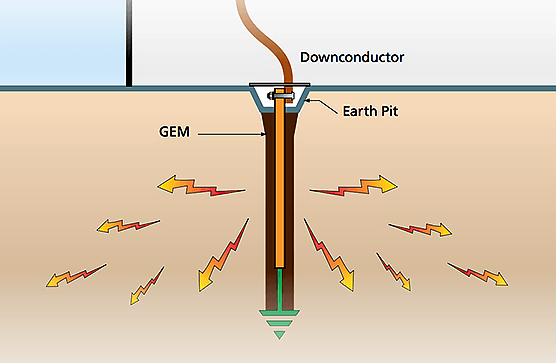
The
primary aim of a direct strike grounding system is to efficiently
dissipate lightning energy into the ground and to help protect equipment
and personnel.
Earthing Principles
Low impedance is the key to lightning protection.
All earthing connections should be as short and direct as possible to
minimize inductance and reduce peak voltages induced in the connections.
The ground electrode system must efficiently couple lightning surges
into the ground by maximizing capacitive coupling to the soil.
The
resistance of the ground itself to lightning currents must also be
minimized. Only when all these factors are taken into account will maximum lightning protection be achieved.
Ground Impedance
Soil resistivity
is an important design consideration. It varies markedly for different
soil types, moisture content and temperatures and gives rise to
variations in ground impedances.
The voltage generated by a lightning discharge
depends primarily on the risetime of the current and the impedance
(primarily inductance) of the path to ground. Extremely fast rise times
result in significant voltage rises due to any series inductance
resulting from long, indirect paths, or sharp bends in the routing of
ground conductors. This is why short, direct ground connections are important.
Electrical
equipment uses a wide variety of wire and cable types and it is up to
us to be able to correctly identify and use the wires which have been
specified. The wrong wire types will cause operational problems and could render the unit unsafe.
Such factors include:
The insulation material;
The size of the conductor;
What it’s made of;
Whether it’s solid or stranded and flexible.
These are all considerations which the designer has to take into account to suit the final application of the equipment.
A
conductor is a material which will allow an electric current to flow
easily. In the case of a wire connection, it needs to be a very good
conductor. Good conductors include most metals. The most common
conductor used in wire is copper, although you may come across others such as aluminium. An insulator on the other hand is a material which does not allow an electric current to flow. Rubber and most plastics are insulators.
Insulation materials
Wires and cables (conductors) are insulated and protected by a variety of materials (insulators)
each one having its own particular properties. The type of material
used will be determined by the designer who will take into account the
environment in which a control panel or installation is expected to
operate as well as the application of individual wires within the panel.
As part of the insulating function, a material may have to withstand without failing:
Extremes of current or temperature;
A corrosive or similarly harsh environment;
Higher voltages than the rest of the circuit.
Because
of these different properties and applications, it is essential that
you check the wiring specification for the correct type to use.
Automated manufacturing systems
operate in the factory on the physical product. They perform operations
such as processing, assembly, inspection, or material handling, in some
cases accomplishing more than one of these operations in the same
system.
They are called automated because they perform their operations with a reduced level of human participation compared with the corresponding manual process. In some highly automated systems, there is virtually no human participation.
Companies
undertake projects in manufacturing automation and computer-integrated
manufacturing for a variety of good reasons. Some of the reasons used to
justify automation are listed below. Of course, there are many other
reasons, so feel free to add your reasons below in the comment box.
Also, I’ve put few interesting videos with latest news in automation of manufacturing processes at the bottom of this article. Enjoy!
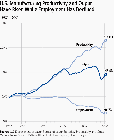
1. To increase labor productivity
Automating a manufacturing operation usually increases production rate and labor productivity. This means greater output per hour of labor input.
2. To reduce labor cost
Ever-increasing labor cost
has been and continues to be the trend in the world’s industrialized
societies. Consequently, higher investment in automation has become
economically justifiable to replace manual operations.
Machines
are increasingly being substituted for human labor to reduce unit
product cost. While this is not good for people, it’s good enough for
production. Sad but true, isn’t it?
3. To mitigate the effects of labor shortages
There is a general shortage of labor in some countries, and this has stimulated the development of automated operations as a substitute for labor.
4. To reduce or eliminate routine manual and clerical tasks
An
argument can be put forth that there is social value in automating
operations that are routine, boring, fatiguing, and possibly irksome.
Automating such tasks serves a purpose of improving the general level of working conditions.
General recommendation is to properly design and implement the facility’s grounding system
to avoid unwanted involvement of ground loops with the operation of the
equipment. This kind of approach can also eliminate the need to
consider equipment modifications and to engage in costly diagnostic
efforts since most trouble involving common-mode noise is avoided in the
signal circuits.
It is generally not possible in complex systems with interconnected data and signal conductors to avoid all ground loops.
Some eight tips that may be used to avoid the detrimental effects of such ground loops include:
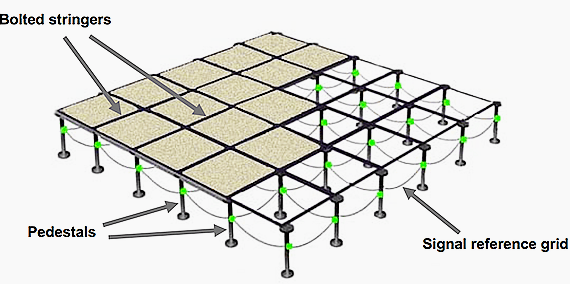
Tip #1 Where possible, cluster the interconnected electronic equipment into an area that is served by a single signal reference grid (SRG).
If the interconnected equipment is located in separate, but adjacent
rooms, then a common signal reference grid should serve all the rooms.
Tip #2 Effectively bond each frame/enclosure of the interconnected equipment to the SRG. In this way, the SRG acts like a uniformly shared ground reference
that maintains a usefully low impedance over a very broad range of
frequency. Typically, from dc to several tens of MHz, for example.
One type of feedback frequently needed by
industrial-control systems is the position of one or more components of
the operation being controlled. Sensors are devices used to provide information on the presence or absence of an object. Siemens
sensors include limit switches, photoelectric, inductive, capacitive,
and ultrasonic sensors. These products are packaged in various
configurations to meet virtually any requirement found in commercial and
industrial applications. Each type of sensor will be discussed in
detail.
At the end of the course an application guide is provided to help determine the right sensor for a given application.
Technologies
Limit switches use a mechanical actuator input, requiring the sensor to change its output when an object is physically touching the switch.
Sensors, such as photoelectric, inductive, capacitive, and ultrasonic, change their output when an object is present, but not touching the sensor.
In
addition to the advantages and disadvantages of each of these sensor
types, different sensor technologies are better suited for certain
applications. The following table lists the sensor technologies that
will be discussed in this course.
Contact Arrangement
Contacts are available in several configurations. They may be normally open (NO), normally closed (NC), or a combination
of normally open and normally closed contacts. Circuit symbols are used
to indicate an open or closed path of current flow. Contacts are shown
as normally open (NO) or normally closed (NC).
The
standard method of showing a contact is by indicating the circuit
condition it produces when the contact actuating device is in the deenergized or nonoperated state.
For
the purpose of explanation in this text a contact or device shown in a
state opposite of its normal state will be highlighted. Highlighted
symbols used to indicate the opposite state of a contact or device are
not legitimate symbols.