Thursday, January 14, 2016

9 Reasons for Automation of Manufacturing Processes


Manufacturing automation

Automated manufacturing systems operate in the factory on the physical product. They perform operations such as processing, assembly, inspection, or material handling, in some cases accomplishing more than one of these operations in the same system.
They are called automated because they perform their operations with a reduced level of human participation compared with the corresponding manual process. In some highly automated systems, there is virtually no human participation.
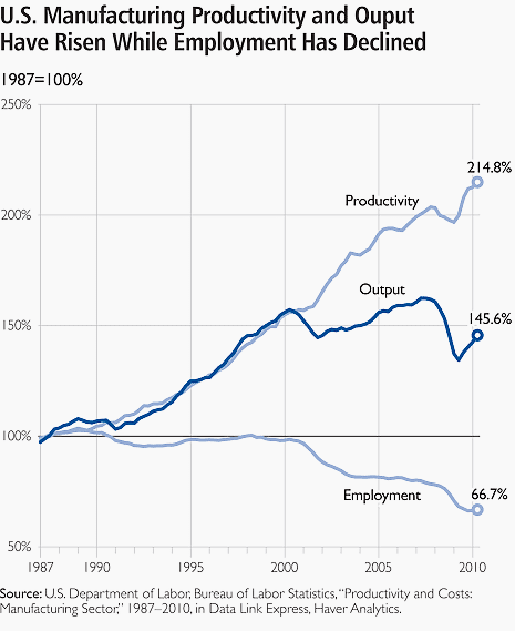
US manufacturing productivity and output chartCompanies undertake projects in manufacturing automation and computer-integrated manufacturing for a variety of good reasons. Some of the reasons used to justify automation are listed below. Of course, there are many other reasons, so feel free to add your reasons below in the comment box.
Also, I’ve put few interesting videos with latest news in automation of manufacturing processes at the bottom of this article. Enjoy!

1. To increase labor productivity

Automating a manufacturing operation usually increases production rate and labor productivity. This means greater output per hour of labor input.

2. To reduce labor cost

Ever-increasing labor cost has been and continues to be the trend in the world’s industrialized societies. Consequently, higher investment in automation has become economically justifiable to replace manual operations.
Machines are increasingly being substituted for human labor to reduce unit product cost. While this is not good for people, it’s good enough for production. Sad but true, isn’t it?

3. To mitigate the effects of labor shortages

There is a general shortage of labor in some countries, and this has stimulated the development of automated operations as a substitute for labor.

4. To reduce or eliminate routine manual and clerical tasks

An argument can be put forth that there is social value in automating operations that are routine, boring, fatiguing, and possibly irksome. Automating such tasks serves a purpose of improving the general level of working conditions.


Click here for the full article


Wednesday, January 6, 2016

8 tips to avoid ground loops when dealing with signal level circuits


Ground loops and signal noise

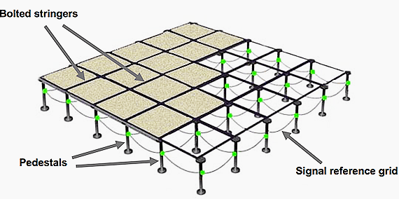
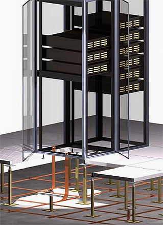
 Example of a signal reference gridGeneral recommendation is to properly design and implement the facility’s grounding system to avoid unwanted involvement of ground loops with the operation of the equipment. This kind of approach can also eliminate the need to consider equipment modifications and to engage in costly diagnostic efforts since most trouble involving common-mode noise is avoided in the signal circuits.
It is generally not possible in complex systems with interconnected data and signal conductors to avoid all ground loops.
Some eight tips that may be used to avoid the detrimental effects of such ground loops include:


Tip #1
Where possible, cluster the interconnected electronic equipment into an area that is served by a single signal reference grid (SRG). If the interconnected equipment is located in separate, but adjacent rooms, then a common signal reference grid should serve all the rooms.

Effectively bond each frame/enclosure of the interconnected equipment to the SRGTip #2
Effectively bond each frame/enclosure of the interconnected equipment to the SRG. In this way, the SRG acts like a uniformly shared ground reference that maintains a usefully low impedance over a very broad range of frequency. Typically, from dc to several tens of MHz, for example.

Click here to read the full article


Basics of Sensors


Sensors

One type of feedback frequently needed by industrial-control systems is the position of one or more components of the operation being controlled. Sensors are devices used to provide information on the presence or absence of an object.
Siemens sensors include limit switches, photoelectric, inductive, capacitive, and ultrasonic sensors. These products are packaged in various configurations to meet virtually any requirement found in commercial and industrial applications. Each type of sensor will be discussed in detail.
At the end of the course an application guide is provided to help determine the right sensor for a given application.

Technologies

Limit switches use a mechanical actuator input, requiring the sensor to change its output when an object is physically touching the switch.
Sensors, such as photoelectric, inductive, capacitive, and ultrasonic, change their output when an object is present, but not touching the sensor.
In addition to the advantages and disadvantages of each of these sensor types, different sensor technologies are better suited for certain applications. The following table lists the sensor technologies that will be discussed in this course.

Contact Arrangement

Contacts are available in several configurations. They may be normally open (NO), normally closed (NC), or a combination of normally open and normally closed contacts. Circuit symbols are used to indicate an open or closed path of current flow. Contacts are shown as normally open (NO) or normally closed (NC).
The standard method of showing a contact is by indicating the circuit condition it produces when the contact actuating device is in the deenergized or nonoperated state.
For the purpose of explanation in this text a contact or device shown in a state opposite of its normal state will be highlighted. Highlighted symbols used to indicate the opposite state of a contact or device are not legitimate symbols.

Click here for the full article


Wednesday, December 2, 2015

The Essentials of Electronics and Electrical Equipment: Shielding

Effective EMI control prevents spurious signals from entering or leaving an enclosure. Shields and filters are the predominant techniques for controlling EMI.

Shields can involve many combinations of foils, conductive inks, paper, and adhesives. For example, there are now shields that consist of silver ink printed on 5-mil-thick polyester. After printing, a curing process removes nonconductive solvents. The result is a homogeneous shield that does not crack or delaminate when bent. The shield can be mechanically fastened and grounded with solder tabs. The cost is about the same as that for conventional laminated designs.

Carbon and stainless-steel fibers, combined with thermoplastics, provide an effective shield in many applications. Carbon fibers are usually classified as either PAN (polyacrylonitrile) or pitch. PAN fiber composites are selected for their high strength. Also, because PAN fiber has a higher aspect ratio (length to diameter ratio) than pitch, less is needed to provide a given conductivity.

Pitch-based fibers are not as strong as low-modulus PAN fibers. However, pitch fibers process easily into high-modulus products, making them attractive for stiffness-critical and thermally sensitive applications. The third carbon additive commonly used is carbon black. Carbon-black plastics are inexpensive, and are primarily for applications requiring high surface conductivity that allows dissipation of static charge.

Five factors affect plastic conductivity. The first is fill aspect ratio, which is proportional to conductivity. Second is loading level, also proportional to conductivity. The lowest fill loading needed to produce conductivity (generally defined as 105Ω/sq) is called the critical concentration.
The third factor is resin type. The amount of fill needed for the critical concentration depends on the resin. For example, because nylon has a crystalline structure, its surface becomes conductive at lower fill concentrations than materials such as amorphous polycarbonate.


Click here to access the full article

Motion Control: Basic Types

Definitions of motion control vary widely in industry today. Depending on the application, motion control can refer to simple on-off control or a sequencing of events, controlling the speed of a motor, moving objects from one point to another, or precisely constraining the speed, acceleration, and position of a system throughout a move.

Engineers working for the first time in some aspect of motion control may be confused by varying interpretations used in the field. Motion control means different things to different sections of industry. As an introduction, this chapter differentiates among motion-control techniques. It puts each technique into perspective in terms of where typical applications arise.

In many cases, motion-control techniques are intimately tied to the controller as well as to the positioning hardware and actuator. No overview of motion control would be complete without a discussion of the various control options that are widely used. These include simple timers and counters, chip-level and board-level computers, programmable logic controllers, and pneumatic sequencers.

 Industrial motion control can be divided into four categories: sequencing, speed control, point-to-point control, and incremental motion.


Click here fore the full article

Tuesday, November 17, 2015

Comparison of Motor Speed Control Methods

Why motor speed control?

It is often desirable to control the motor speed, usually for reasons process control for such variables as flow or pressure. Such applications as fans and pumps often have varying output requirements, and control of the motor speed is more efficient than mechanically limiting the process output with such devices as throttling valves or dampers.


The reason for this is due to the fact that for centrifugally-based processes (such as fans and centrifugally-based pumps), the following relationships exist:

Torque = RPM2
Power = RPM3

So, for these types of processes the torque required to turn them is proportional to the square of the speed.

Comparison of Motor Speed Control Methods

But, the power required to turn them is proportional to the cube of the speed, and this is what makes motor speed control economically attractive. To further this argument, consider the energy wasted when mechanical means such as the throttling valves or dampers are used to control a process which is being driven from a motor running at full speed.
 
It is clear that motor speed control can be used to save energy by reducing wasted energy used to mechanically control the process.

Adjustable-speed drives (ASDs)

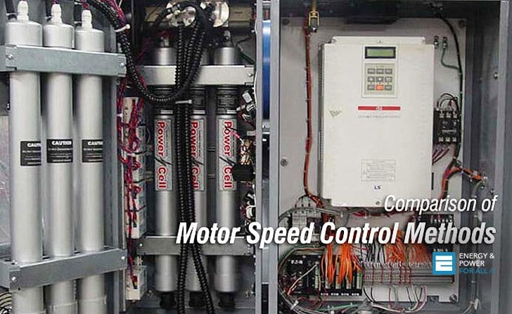
By far the most commonly-used AC motor control method is the use adjustable-speed drives. In most commercial and industrial environments these have supplanted virtually every other motor speed control method.
An adjustable-speed drive works on the principle of varying the frequency to vary the speed of the motor. Recall that from equations above the synchronous speed of a motor is a function of both the system frequency and the number of poles of the motor. By varying the frequency, the motor speed may be varied so long as the motor is equipped to dissipate the heat at reduced speeds.
Unlike soft-starting, specialized definite-purpose inverter-rated motor designs are preferred since reduced-speed operation can cause thermal issues and overspeed operation can result in safety issues.

Further, pulse-width modulated (PWM) drive outputs can cause repetitive voltage overshoots referred to as ringing, which can reduce the life expectancy of a general-purpose motor. The motor manufacturer should be consulted before applying a general-purpose motor in an adjustable-speed drive application.


Click here for full article

Thursday, November 12, 2015

Connections For Testing Insulation Resistance Of Electrical Equipment

Testing Insulation Resistance //

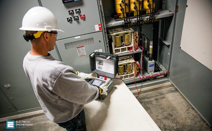
The following schemes show how to connect a Megger insulation tester to various types of electrical equipment. The schemes also show in principle how equipment must be disconnected from other circuits before the instrument is connected.
Connections For Testing Insulation Resistance Of Electrical Equipment
These illustrations are typical and will serve as guides for testing insulation resistance of practically all types of apparatus and conductors. Before proceeding with tests, read the part on Preparation of apparatus for test at the bottom of this article.

REMEMBER! The Megger insulation resistance tester measures whatever resistance is connected between its terminals. This may include series or parallel leakage paths through insulation or over its surface.

Electrical equipment to test //

  1. AC Motors and Starting Equipment
  2. DC Generators and Motors
  3. Wiring Installation
  4. Appliances, Meters, Instruments and Other Electrical Apparatus
  5. Control, Signaling and Communication Cables
  6. Power Cables
  7. Power Transformers
  8. AC Generators

Important //


1. AC Motors and Starting Equipment

Connections for testing the insulation resistance of a motor, starting equipment and connecting lines, in parallel. Note that the starter switch is in the “on” position for the test. It is always preferable to disconnect the component parts and test them separately in order to determine where weaknesses exist.
Testing the insulation resistance of a motor


Figure 1 – Testing the insulation resistance of a motor
 
 
Click here to access the full article