Thursday, September 13, 2012

Crimping Technology for Industrial Connectors 101


How do you achieve the best-possible crimping in accordance with the industry safety standards?

The quality of an electrical connection depends to a great extent on the choice of suitable components in the respective nominal section widths and using recommended tools for processing.
Size differences between the cable and the connector (pipe-type cable lug/multicore cable end) are the result when only one crimp contact lead in class 5 und 6 - even with different structure (bunched conductor, stranded or compressed strand) could be compressed. Despite what appear visually to the sleeves, the correct combination of conductor, contact and tool can provide "gas-tight" crimping. The dimensional stability on the above-mentioned connecting points is guaranteed by, among other things, the following standards: 

• DIN EN 60228 (VDE 0295), September 2005 "Conductors for cables and insulated lines"
The content of the standard includes among other things the maximum wire diameter and the maximum conductor resistance for the respective nominal cross sections (mm²), but not however, the number of wires or the structure. Improved technologies in the area of copper production mean that the conductor resistance specified in the standard can now be achieved with reduced cross sections. 

• DIN 46228 – 4, September 1990 "Multicore cable ends – tube-type with plastic sleeve" 

• Quality of crimping as per DIN 46228 – 1 and DIN EN 50027

 
Should connectors be crimped or soldered together? 

The crimp connection is the best type of connection for all loaded applications. The advantage compared against all other connection contact cables is - 100% process-consistent fabrication and quality control in accordance with safety standards. Full compliance to safety standards will guarantee tensile strength, current load and forward resistance.

Solder connection on the other hand whether "soldered by hand" or automatically soldered" can affect the overall quality of the soldering points based on:

- the experience of the person doing the soldering
- temperature changes and movement, as the soldering point can deteriorate as time passes (problems that occur with the electronics/electrical system are often down to "dry solder joints" - in other words, poor contact)


Wednesday, September 5, 2012

Industrial Wire & Cable Flammability Test Methods


Testing is a very critical aspect of Wire & Cable manufacturing. They are a very wide array of safety standards to comply with which can be very confusing. For example, flame resistance and fire propagation tests are often confused with one another on the basis of their very similar designations. However, the test methods employed are quite different:


IEC 60332-1-2: Test for vertical flame propagation for a single insulated wire or cable
 
This flame resistance test is passed by most cables constructed of flame-retardant materials, e.g. PVC and chloroprene rubber, or materials with special flame-retardant additives such as PUR. In the test, a single core or cable with a length of approx. 60 cm is mounted vertically using two clamps, after which a pre-defined flame is applied to the bottom end for a period of 60 seconds (or 120 seconds in the case of cable diameters > 25 mm). The test is deemed passed if, after the flame has been removed, the burning cable extinguishes itself and the fire damage is at least 50 mm from the upper mounting clamp. It is irrelevant how long the cable burns before extinguishing itself.


IEC 60332-3: Test for vertical flame spread of vertically-mounted bunched wires or cables
 
This fire propagation test is also known as the "bundle fire test" and is generally only passed by specially developed cables and wires with highly flame-retardant insulation and sheath material. In most cases, the flame resistance of the plastics used is greatly enhanced by the addition of aluminium or magnesium hydroxide. Multiple cables are bundled or layered in lengths of approx. 3.5 m and vertically affixed to a ladder-like metal structure, after which a flame is applied to the lower end of the cables using a propane burner. The cable volume and time of flame application is defined by the test method, since IEC 60332-3 comprises four different bundle fire tests:

• IEC 60332-3-22 Category A:    7 liters of combustible material per meter / flame application: 40 minutes
• IEC 60332-3-23 Category B:   3.5 liters of combustible material per meter / flame application: 40 minutes
• IEC 60332-3-24 Category C:   1.5 liters of combustible material per meter / flame application: 20 minutes / cable diameter > 12.0 mm
• IEC 60332-3-25 Category D:   0.5 liters of combustible material per meter / flame application: 20 minutes / cable diameter< 12.0 mm

IEC 60332-2-22 Category A is often used for maritime applications on oil rigs and ships, for example. The test is deemed passed if, after the burner has been switched off, the burning cables extinguish themselves and the fire damage does not cover more than 2.5 m measured from the bottom cable end. It is impossible to say which of the four test categories poses the most difficult challenge, since there are a range of different factors to consider.


IEC 60331: Functional integrity and fire resistance of electric cables
 
Unlike IEC 60332-1-2 and IEC 60332-3, this test does not assess the flame propagation but instead checks the electrical functioning of the cable in the event of a fire. In the test, a flame is applied across the entire horizontal length of a single, 120 cm cable for a period of 90 minutes. The test is deemed passed, if the cable continues to conduct electricity without shorting throughout the 90 minute flame application and for a subsequent 15 minute cooling period. This test is generally only passed by cables and wires with special, flame-retardant glass or mica wrapping enclosing the individual cores as well as the entire cable bundle.


Visit our website 

Like us on Facebook

Join our Linkedin Network

Tuesday, August 28, 2012

Cable Glands for Full EMI Protection


Winning the war against electromagnetic interference (EMI) on today’s factory floors requires attention to detail. One of those details involves the ability of cable glands to contribute to a reliable grounding system.
Left unprotected, cable glands transmit electrical noise that can wreak havoc on motor-driven industrial processes. Many types of cable glands feature shielding to keep EMI at bay, yet the effectiveness of that shielding  can vary widely from product to product.
The ease of installation can vary as well. Some sheilding options have difficult termination methods or grounding conntections that can drive up labor cost and time.  
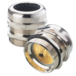
With SKINTOP® MS-M Brush, our engineers have addressed both the shielding and installation issues. As its name suggests, this cable gland features a brush-type grounding connection that:
  Enhances EMI control. Unlike other connection methods, such as the grounding clamps commonly used on drive systems, the brush provides continuous 360° contact around the cable’s screen braid. This continuous contact protects against EMI by lowering the resistance of current ground path and providing a low impedance connection between the cable shield and the housing.
  Eases Installation. Making an EMI-free connection between cable and the SKINTOP cable gland is simple. Installers simply insert the cable, push the screen braid into the brush and tighten the cable gland assembly. Other grounding methods require far more effort to make the termination. Earth sleeves, for example, can serve as an effective grounding method, but their termination process requires precision measurments and exacting preparation of the stripped area.
In addition to its innovative brush-type connection, SKINTOP® MS-M Brush offers IP 68 protection and resists temperatures up to 100ºC. Until recently, it was available only in metric sizes, ranging from M–25X1.5 to M–110X2.0. This month, we’ve introduced NPT sizes from ¾” to 2”.
For detailed technical information on SKINTOP® MS-M Brush, go to http://www.lappusa.com/PDF/Page506-SkintopMSMBrush-BrushPlus.pdf

Monday, August 13, 2012

Krones Puts in the Time for NFPA Compliance

If you find electrical safety standards confusing, you’re not alone. Many machine builders have recently had to grapple with an ambiguous round of changes to NFPA–79, the portion of the National Electrical Code that governs the electrical wiring of industrial machines.

The most important change to NFPA–79 for 2012 involves the ability to use Appliance Wiring Material (AWM), which had been banned since 2007.

AWM can be a cost-effective wiring choice compared to higher-performing UL listed Machine Tool Wire (MTW). And though there had been some [sound technical reasons behind the ban](link to white paper download), high-quality AWM can be a valid wiring choice if properly specified.

One company that has successfully navigated the shoals of the changes related to AWM usage is Krones Inc., a manufacturer and integrator of packaging lines for some of the world’s best known food and beverage companies.

Krones’ engineering team recently found that compliant AWM usage does require a bit of extra effort compared to the automatic compliance found with listed UL wire. “Whenever you have to implement changes to an electrical code, there’s definitely an engineering labor factor,” says Mike Nelson, the Krones engineer charged with NFPA–79 compliance.

Some of that engineering labor has gone into researching into specific AWM products to see whether they meet the compliance restrictions. Even proper jacket labeling doesn’t answer all the compliance questions regarding AWM, “so you can’t tell whether a product complies just by looking at the cable,” says Nelson. More engineering labor has been devoted to NFPA–79’s documentation requirements.

In all, Nelson estimates that Krones has spent more than 150 engineering man hours complying with the requirements related to AWM use. And that figure represents just work done to formulate a compliance strategy. It does not include the technical documentation and drawing changes needed for each and every machine.

For more information about NFPA-79 compliance, download our latest white paper. Or contact the experts one our application engineering team for compliance help.


Visit our website 

Like us on Facebook

Join our Linkedin Network
Industrial Wire & Cable : Back to the Basics


Below is a short list of Frequently Asked Questions about industrial wire & cable design and applications.

Q: How do you convert the alternating current voltage value (AC) of a cable into the corresponding direct current voltage value (DC)?

A: The rated voltage is specified in the form of an AC value (Alternating Current). In a DC system (Direct Current), the rated voltage of the system must not be greater than 1.5 times of the rated voltage of the cable.
To calculate the DC value, the relevant AC value is simply multiplied by a factor of 1.5, as in the examples below:

AC Alternating current          Factor                   DC Direct current
300/500 V                              x 1.5                      450/750 V
450/750 V                              x 1.5                      675/1125 V
600/1000 V                            x 1.5                      900/1500 V

The electrical voltage is measured in Volt (V).

Q: Can the steel wire armor also be used as EMC-compliant electromagnetic shielding resp. screening?

A: Although copper and steel are conductive metals, only copper (e.g. in the form of a braid) represents a suitable means of protecting a cable or wire from electromagnetic interference or shielding the environment from the interfering emissions originating from the cable itself. This not only depends on the electrical conductivity of the metal employed, but also on the braid density or the degree of coverage with which the cable is braided.
From all metals only pure silver offers marginally better conductive performance than copper. Although different qualities of iron/steel alloy exist, the conductivity of steel is generally six times lower than that of electrolyte copper. For this reason, a steel wire braid only ever protects a cable from external mechanical impact. To ensure optimized electromagnetic shielding, which also meets the requirements of the Electromagnetic Compatibility (EMC) directive, a sufficient level of copper braiding is required. As a minimum, a visual coverage level of 82-85% is required to achieve adequate screening protection. In the case of a steel wire braid used solely for mechanical protection, a visual coverage level of approx. 50% or less is standard. With a little practice, it is therefore quite easy to visually distinguish copper and steel wire braids by their degree of coverage. In addition, copper braids often have a slight reddish tinge (despite their tin plating), are somewhat softer than steel and are in comparison to steel non-magnetic.

However, even the densest, highest quality copper braid is rendered useless if it is not properly grounded! For safety reasons, steel wire braids should also be earthed when used in power networks. If the connected equipment develops a fault, this grounding prevents the transmission of dangerous voltages to the often exposed steel wire braid at the connecting points.

Q: Can a data cable with a peak operating voltage of 250 V be used to connect a device with a mains voltage of 230 V?

A: No! This could easily result in fires or lethal electric shocks! Data network cables and power cables are subject to completely different design and test standards. The main difference lies in the core insulation strength. Data cables are typically used in data networks with a voltage range of 6 to 48 V. Connection and control cables, on the other hand, are predominantly used for devices with a 230 V mains voltage (e.g. drills, lawnmowers etc.) or for machines in power or three-phase networks.

Since the size of the voltage is directly connected to the strength of the core insulation, this represents the greatest difference between data and power cables.

To be able to cope with voltage ranges of 300/500 V, the core insulation of power cable, for example, is on average 50-70% thicker than that of a data cable. It is possible for voltage peaks of 250 V to occur in data networks. However, under no circumstances must this voltage be equated with a stabilized alternating current of 230 V at 50 Hz supplied from a mains power socket! Using a data cable in this case would carry a very high risk of cable fires or electrocution resulting from the insufficient strength of the core insulation! The dielectric strength of data cables is generally only checked with 1200 to 1500 V for one minute periods. Connection and control cables, on the other hand, are tested with 4000 V for periods of 15 minutes.

Indirect connection of data cables to the power network is only possible if a transformer is used to convert the mains voltage to the permissible low voltage of the operated device (e.g. a laptop or model railway). In this case, it must be ensured that cable with the appropriate voltage class (e.g. 300/500 V) is used to connect the transformer to the mains supply and that the data cable is only used to link the relevant device with the transformer.

The electrical voltage is measured in Volt (V).


Q: Is it possible to load a cable or wire with a voltage class of 300/500 V with a higher voltage for a brief period, provided that the testing voltage value is not exceeded?

A: Heating systems, for example, require a relatively high voltage to ignite the pilot flame, but this is only needed once or twice a day and for a matter of milliseconds. Operators and users are often of the opinion that a cable with a rated voltage class of, for example, 300/500 V can be briefly supplied with a higher voltage, provided that it does not exceed the specified testing voltage. In such cases, it is very important to note that a cable with a rated voltage class of 300/500 V and a testing voltage of, for example, 4000 V must never be subjected a voltage exceeding the specified rated voltage – not even for a matter of milliseconds! Even if, for example, a voltage of 2500 V occurs just once per day for a single second, the relevant cable, and the core insulation thickness in particular, must be constructed and tested to ensure the appropriate rated voltage. In this particular case, a cable a with a rated voltage class of 1.8/3 kV must be used to safely handle the briefly occurring voltage of 2500 V.


Q: What is the difference between a copper braid screening and an aluminum laminated foil screening?

A: Copper braids primarily protect the cable against inductive coupling in the low frequency range in which virtually all connecting and control cables operate. If, for example, a data cable is installed in the direct vicinity of another connecting cable that may not have copper screen braiding, the data cable should be protected against inductive interference from the connection cable by means of a screening braid. The same applies if a connecting cable is installed in the proximity of an insufficiently shielded or EMC-compliant machine or in the vicinity of an electric motor, which can also generate fields of inductive interference.
Aluminum foils are primarily used in data cables, as data is generally transferred at very high frequencies, thus necessitating protection against capacitive coupling.
The so-called coupling resistance and the transfer impedance act as indicators of the shielding performance – the lower the measured transfer impedance, the greater the effectiveness of the cable screening.

Of course, the best results are achieved by combining a foil shield with copper screen braiding. The disadvantage is that the aluminum foil laminate makes the cable quite stiff and inflexible, meaning that it is mostly only really suitable for fixed installations in conventional cable construction design. Frequent movement of the cable can quickly tear or displace the sensitive foil shield, which will have a negative impact on screening performance.


Visit our website 

Like us on Facebook

Join our Linkedin Network